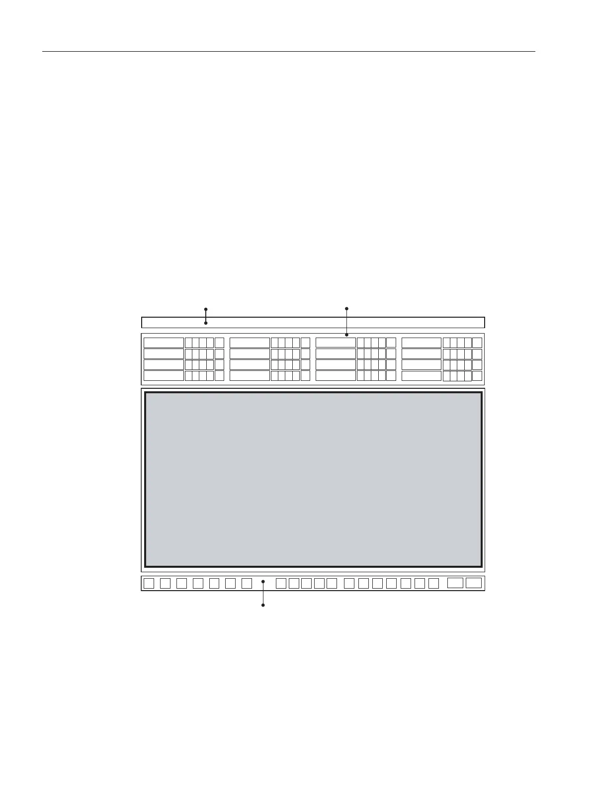
The user interface in process mode is divided into four areas:
● Message line: Displays the most recent message with the highest priority.
● Overview area: You can select the areas of a plant and view them using various command
buttons. In your "color_gs" project, you have only one button, namely "RMT1", because
your plant consists of only one part.
Next to each button there are four other small buttons which you can use to view alarms
and warnings from the sublevel hierarchy. If you click in this area, you can automatically
change to the process picture in which the alarm or warning originated.
The arrow key on the extreme right opens a tree view in which you can select a sublevel
of the hierarchy.
● Process picture: Returns the associated process picture, depending on the area you
selected in the overview. In your "color_gs" project, the plant picture you created in the
Graphics Designer is displayed.
● Button set: Can be used to call various functions which you can select in process mode. In
the "color_gs" project, you will only get to know the buttons that are important for this project.
0HVVDJHOLQH2YHUYLHZDUHD
3URFHVVSLFWXUH
.H\VHW
Working in runtime
10.1 Planning the user interface
PCS 7 SMART Getting Started - Part 1 (V9.0 with APL)
172 Getting Started, 12/2017, A5E42181435-AA