Home
Siemens
Control Systems
SIMATIC PCS 7 SMART
Siemens SIMATIC PCS 7 SMART User Manual
5
of 1
of 1 rating
210 pages
Give review
Manual
Specs
To Next Page
To Next Page
To Previous Page
To Previous Page
Loading...
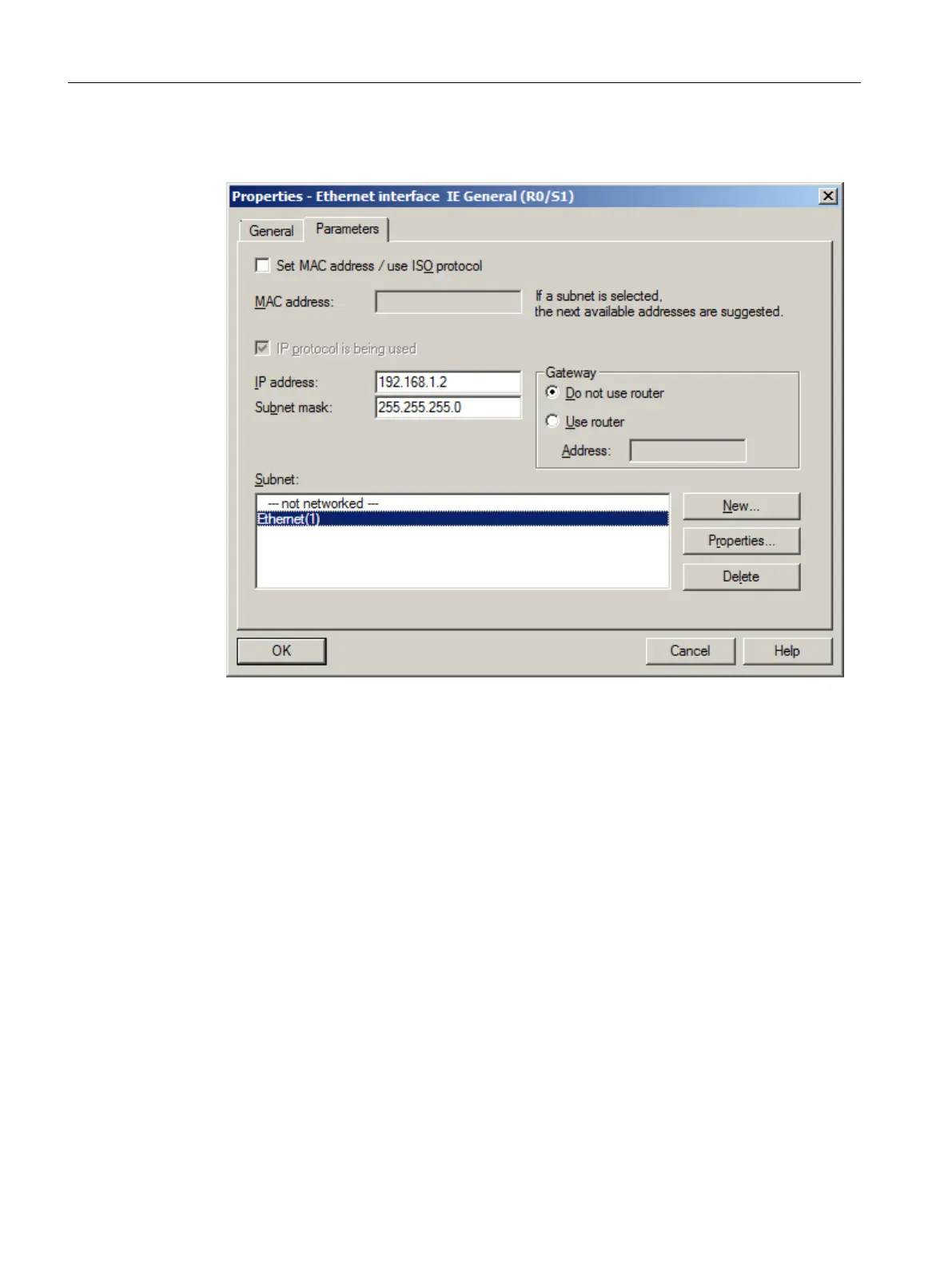
7.
Select "Ethernet(1)" from the "Subnet" list.
This is the connection that you have already configured for the CPU.
Initial work for the project
5.4 Configuring the stations
PCS 7 SMART Getting Started - Part 1 (V9.0 with APL)
46
Getting Started, 12/2017, A5E42181435-AA
45
47
Table of Contents
Default Chapter
3
Table of Contents
3
1 Security Information
9
2 Preface
11
Process Control System PCS
16
3 Requirements for Getting Started
17
Hardware Requirements for Getting Started - Part 1
17
Software Requirements for Getting Started - Part 1
18
Required Configuration for Getting Started - Part 1
19
4 PCS 7 SMART Overview
21
PCS 7 SMART Inclusions
22
Introduction to SIMATIC Manager
23
Basic Structure of SIMATIC Manager
24
Different Views of SIMATIC Manager
25
Procedure
26
Opening SIMATIC Manager
26
5 Initial Work for the Project
27
Planning the Project
27
The "Color_Gs" Project
27
Task List for Getting Started
28
System Configuration for the 'Color_Gs' Project
30
Configuration Tasks Overview
31
Performing the Additional Task
31
Preparational Settings for the Network
32
Network and Interface Settings
32
Procedure
32
Configuration Console Settings
32
Creating the Project
34
New Project" Wizard Usage
34
Background Knowledge for the PCS 7 Wizard
34
Procedure
36
Creating the Color_Gs Project
36
Opening and Closing the "Color_Gs" Project
39
How to Work in the Various Views
39
Configuring the Stations
41
Configuration Overview
41
Procedure
42
AS Configuration
42
Renaming the PC Station
44
Configuring the PC Station of the os
45
Netpro Settings
47
Configuring and Downloading the PC Station of the os
49
Downloading the Hardware Configuration of the as
50
Working in the Plant Hierarchy
52
Introduction to Plant Hierarchy
52
Plant Hierarchy Settings
52
Plant View Structure
54
Adapting Default Names
54
Inserting Additional Hierarchy Folders
57
Checking the Assignment of AS/OS to the Plant Hierarchy
58
Current Status
59
Current State of Your Project
59
6 Creating Cfcs
61
CFC Charts and the CFC Editor
61
Working with Libraries
62
CFC Charts and the Master Data Library
62
Storing Objects in the Master Data Library
62
Working with the Master Data Library
63
Opening the Libraries
64
Storing Blocks
65
Storing Process Tag Types
67
Showing and Hiding Libraries
68
Process to Hide and Show Libraries
69
Technological Significance of the Charts in the Project
71
Charts in "Color_Gs" Project
71
Process-Related Meaning of the "CFC_SETP" CFC Chart
71
Process-Related Meaning of the "CFC_FC111" CFC Chart
72
Process-Related Meaning of the "CFC_LI111" CFC Chart
72
Process-Related Meaning of the "CFC_NP111" CFC Chart
72
Process-Related Meaning of the "Cfc_Nk11X" CFC Chart
73
Cfcs in the Plant Hierarchy
74
Working with CFC Charts
74
Procedure
74
Renaming CFC Charts in the Plant Hierarchy
74
Inserting New CFC Charts in the Plant Hierarchy
75
Inserting the "Motor_Lean" Process Tag Type
76
The Current Status
77
Current Status of Your Project
77
Working with the CFC Editor
78
Introduction to the CFC Editor
78
CFC Chart in the CFC Editor
78
Catalog in the CFC Editor
79
Configuration Steps for CFC Charts Overview
80
Opening the "CFC_SETP" CFC Chart
80
Assignment of Block Parameters in CFC Charts
81
Inserting the Blocks into the "CFC_SETP
81
Assigning Parameters for the Blocks in "CFC_SETP
82
Inserting the Blocks into the "CFC_FC111
84
Assigning Parameters for the Blocks in the "CFC_FC111
85
Inserting the Blocks in the "CFC_LI111
88
Assigning Parameters for the Blocks in the "CFC_LI111
89
Assigning Parameters for Blocks in the "CFC_NP111
91
Interconnection of Blocks in the CFC Charts
92
Interconnecting Blocks in the "CFC_NP111
93
Interconnecting Blocks in the "CFC_FC111
94
Interconnecting Blocks in the "CFC_LI111
95
Assigning Parameters for the Blocks in "Valve_Lean
96
Interconnecting the Blocks in "Valve_Lean
97
Cfcs in the Process Object View
98
Use of the Process Object View for Valve Control
98
Procedure
98
Defining Inputs/Outputs for the Process Object View
98
Inserting the "Valve_Lean" Process Tag Type
100
Adapting the Parameters for "Cfc_Nk11X
101
Deleting Interconnections to Addresses
103
Selecting Block Icons
104
The Current Status
105
Current Status of Your Project
105
7 Creating Sfcs
107
Overview of Sequential Function Charts (Sfcs)
107
Working with the SFC Editor
108
Introduction to the SFC Editor
108
Important Functions in the SFC Editor
108
Properties of Steps and Transitions
109
Overview of the Configuration Steps for SFC Charts
110
Moving an SFC Chart
110
Renaming the SFC Chart
111
Opening the "SFC_RMT1" SFC Chart
112
Technological Structure of the Sequential Control System
112
Creating the Sequential Control System in the SFC Chart
113
Renaming Steps
115
Renaming Transitions
117
Setting Parameters
119
Assigning Parameters to the Steps of the SFC Chart
119
Parameters for the Steps
122
Assigning Parameters to the Transitions of the SFC Chart
124
Parameters for the Transitions
125
Optimizing the Run Sequence
127
The Current Status
128
Current Status of Your Project
128
8 Compiling, Downloading and Testing the Charts
129
Overview of Compiling, Downloading, and Testing
129
Procedure
130
Compiling and Downloading CFC and SFC Charts
130
Testing the Program
133
Testing the Program in the SFC Editor
134
Testing the Program in the CFC Editor
135
The Current Status
137
Current Status of Your Project
137
9 Configuring the Operator Station
139
Introduction to the os Project Editor
139
Operator Station in Process Mode
140
Configuration of the Operator Station
141
Working in the SIMATIC Manager
142
Preparations in SIMATIC Manager
142
Procedure
143
Editing Picture Properties
143
Deleting Unnecessary Pictures
144
Creating Block Icons
145
Compiling the os
147
Starting the PCS7 SMART os
150
Working on the os
151
Structure of the os - Wincc Explorer
151
Function of Process Pictures
151
Setting the os Activation for the es
151
Working in General with the Graphics Designer
153
Introduction to the Graphics Designer
153
Opening a Process Picture
153
Opening Various Toolbars
154
Objects in the Graphics Designer
155
Static Objects
156
Text Fields
156
Working with Tag Interconnection
156
Creating the Process Picture
157
Inserting Pipes and a Tank into the Process Picture
157
Labeling the Parts of the Plant
160
Step 1 - Inserting a Text Field
160
Step 2 - Setting the Text Field
160
Step3 - Duplicating the Text Field
161
Current Status of the Process Picture
163
Adapting Process Pictures
163
Connecting the Raw Material Tank with the Process Value
164
Step 3 - Adding Explanatory Text
167
Step 4 - Configuring the Setpoint Default
168
Completing the Work
169
The Current Status
170
Current Status of Your Project
170
10 Working in Runtime
171
Planning the User Interface
171
Operator Station in Process Mode
171
User Interface in Process Mode
171
Operator Control and Monitoring in Process Mode
173
Wincc Language Settings
173
Activating Process Mode
173
Starting the Process
174
Stopping the Process
177
Controlling the Process by Means of the Process Picture
177
Specifying the Reactor
177
Opening the Faceplates
178
Changing the Setpoint
178
Working with Messages
182
Process Mode Exit
184
11 Performing the Additional Task
185
Introduction to the Additional Task
185
Copying the Existing 'RMT1' Part of the Plant
186
Process Mode Preparation
188
Compile and Download the Changes
189
Adapting the os Configuration
194
Starting Process Mode
195
12 Starting and Adapting the Color_Gs Project
197
Color_Gs Project
197
Procedure
198
Opening the Color_Gs Project
198
Adapting the Hardware for the Color_Gs Project
198
Adapting the Blocks for the Color_Gs Project
199
Adapting the Project Data for the Color_Gs Project
200
Compiling and Downloading the Color_Gs Project
201
Index
205
5
Based on 1 rating
Ask a question
Give review
Questions and Answers:
Need help?
Do you have a question about the Siemens SIMATIC PCS 7 SMART and is the answer not in the manual?
Ask a question
Siemens SIMATIC PCS 7 SMART Specifications
General
Brand
Siemens
Model
SIMATIC PCS 7 SMART
Category
Control Systems
Language
English
Related product manuals
Siemens SIMATIC PCS 7
240 pages
Siemens SIMATIC PCS 7 OSx
232 pages
Siemens SIMATIC OpenPCS 7
96 pages
Siemens PCS 7
156 pages
Siemens SIMATIC PCS7
286 pages
Siemens SIMATIC OP7
44 pages
Siemens SIMATIC BATCH
1158 pages
Siemens simatic c7-621
20 pages
Siemens SIMATIC C7-613
200 pages
Siemens SIMATIC C7-635
92 pages
Siemens SIMATIC HMI KTP400
36 pages
Siemens SIMATIC S5 CPU Series
18 pages