Procedure
1. Open the "General" tab and "Inputs/Outputs" tab in the "Object Properties" dialog box for
each block.
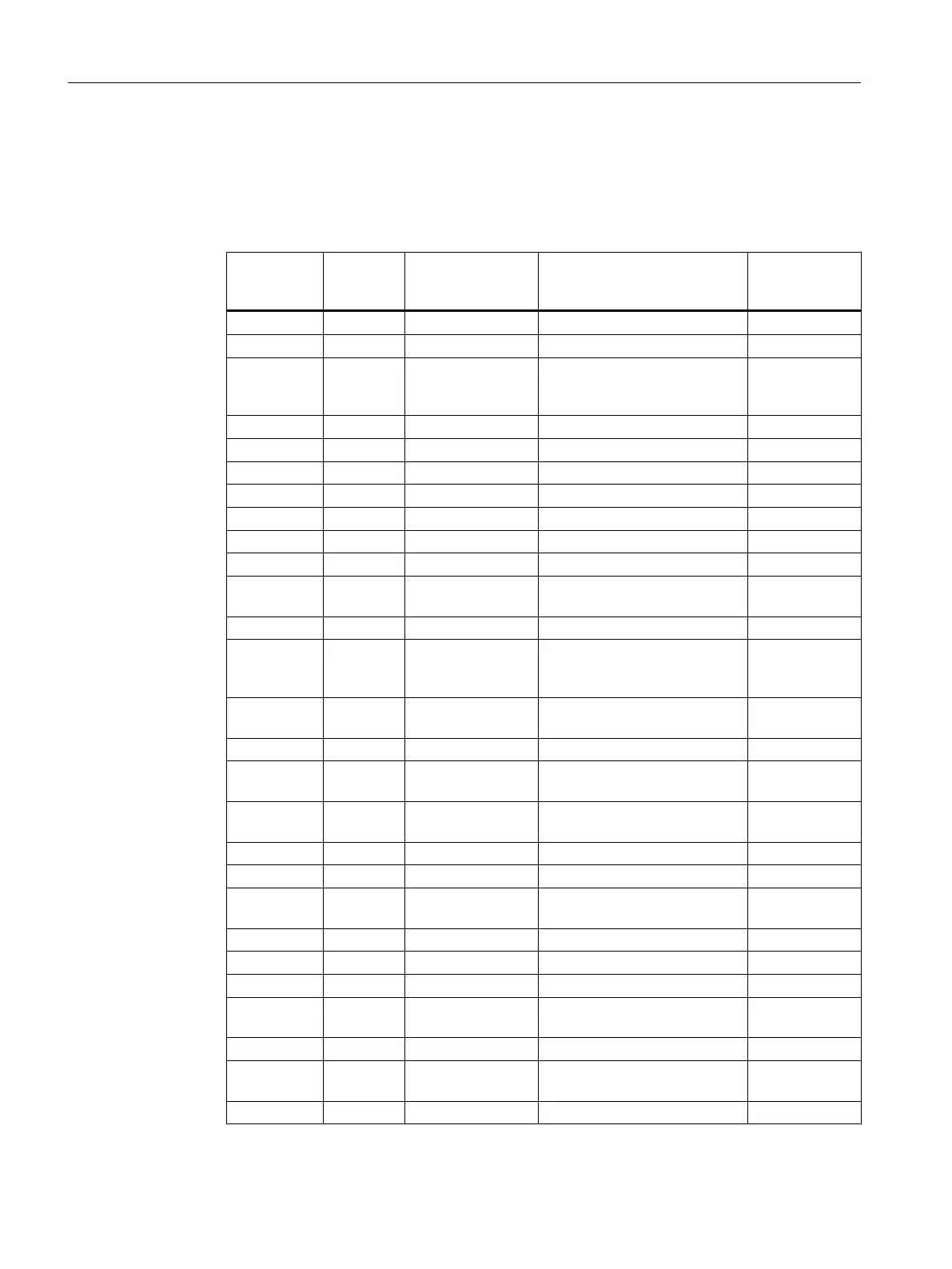
2. Enter the parameters for all blocks according to the table below.
Block Block
name in
the project
I/O Meaning Value
Mul04 4 In1.ST Value 1 to multiply (BYTE) 0
In1.Value Value 1 to multiply (REAL) 0
In4.Value Invert sign for flow rate (proc‐
ess value) - Part of the fill level
simulation in raw materials tank
-1.0
Pcs7AnIn INPUT_U Feature.Bit29 Enables a substitute value 1
Mode Measuring range 4 to 20 mA 16#0203
Scale.High High measuring range 550
SimOn.Value Simulation value active 1
SimPV_In.Value Raw materials tank level 500
SubsPV_In Substitute value for SimPV_In 500
Integral INT_P In.ST Analog input value (BYTE) 0
In.Value Simulation of the raw material
tank level
0.0
OutHiLim High limit of the output value 500
OutTrk.ST Predefined value used for Out‐
TrkOn = 1 (BYTE)
0
OutTrk.Value Predefined value used for Out‐
TrkOn = 1 (REAL)
0
TI Integration time 30
MonAnL LIA GradHDnEn Gradient monitoring (high) for
negative changes
0
GradHUpEn Gradient monitoring (high) for
positive changes
0
PV.ST Process value (BYTE) 0
PV.Value Process value (REAL) 0
PV_AH_En PV alarm limit (high) deactiva‐
ted
0
PV_AH_Lim High alarm limit = 490 m
3
490
PV_AL_Lim Low alarm limit = 5 m
3
25
PV_Hyst Hysteresis 1
PV_OpScale.High High display limit of the proc‐
ess value in the container
550
PV_Unit Unit of the PV in m3 1034
PV_WH_En PV warning limit (high) deacti‐
vated
0
PV_WH_Lim High warning limit = 450 m
3
450
Creating CFCs
6.6 Working with the CFC Editor
PCS 7 SMART Getting Started - Part 1 (V9.0 with APL)
90 Getting Started, 12/2017, A5E42181435-AA