Parameterization 03.2010
6SE7087-6QX70 (Version AL) Siemens AG
5-14 Compendium Motion Control SIMOVERT MASTERDRIVES
USS-Bus
Jog 7 8 9
P
Reset
+/-0
456
123
O
I
Fault
Run
SIEMENS SIEMENS
X100
Run
Failure
Chopper
activ e
SIEMENS
A
S1
BX101
CX103
SIEMENS
A
S1
BX101
CX103
SIEMENS
A
S1
BX101
CX103
SIEMENS
A
S1
BX101
CX103
SIEMENS
A
S1
BX101
CX103
SIEMENS
A
S1
BX101
CX103
SIEMENS
A
S1
BX101
CX103
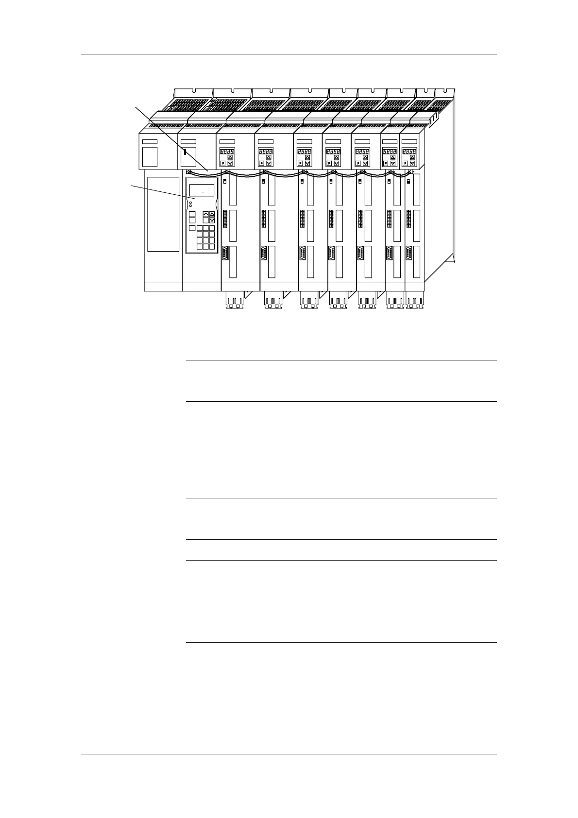
USS bus
on X100
OP1S mounted
on rectifier unit
CM Rect.Unit Inv Inv Inv Inv Inv Inv Inv
Fig. 5-6 Example: The OP1S during bus configuration with Compact PLUS units
During bus operation, the Compact PLUS rectifier unit is only for
mechanically restraining the OP1S and for connecting the bus to the
inverters. It does not function as a slave.
5.4.2.2 Run-up
After the power su
pply for the unit connected to the OP1S has been
turned on or after the OP1S has been plugged into a unit which is
operating, there is a run-up phase.
The OP1S must not be plugged into the Sub D socket if the SCom1
interface parallel to the socket is already being used elsewhere, e.g.
bus operation with SIMATIC as the master.
In the as-delivered state or after a reset of the parameters to the factory
setting with the unit's own control panel, a point-to-point link can be
adopted with the OP1S without any further preparatory measures.
When a bus system is started up with the OP1S, the slaves must first
be configured individually. The plugs of the bus cable must be removed
for this purpose (see section "Bus operation").
NOTE
NOTICE
NOTE