Communication / USS 02.2004
6SE7087-6QX70 (Version AD) Siemens AG
8.1-28 Compendium Motion Control SIMOVERT MASTERDRIVES
8.1.4.4 Bus termination, USS protocol
In order to ensure interference-free USS operation, the bus cable must
be terminated with bus terminating resistors at both ends. The bus
cable from the first USS node to the last USS node is to be regarded as
one bus cable. The USS bus therefore must be terminated twice. The
bus terminating resistors must be switched in at the first bus node (e.g.
master) and last bus node (e.g. converter).
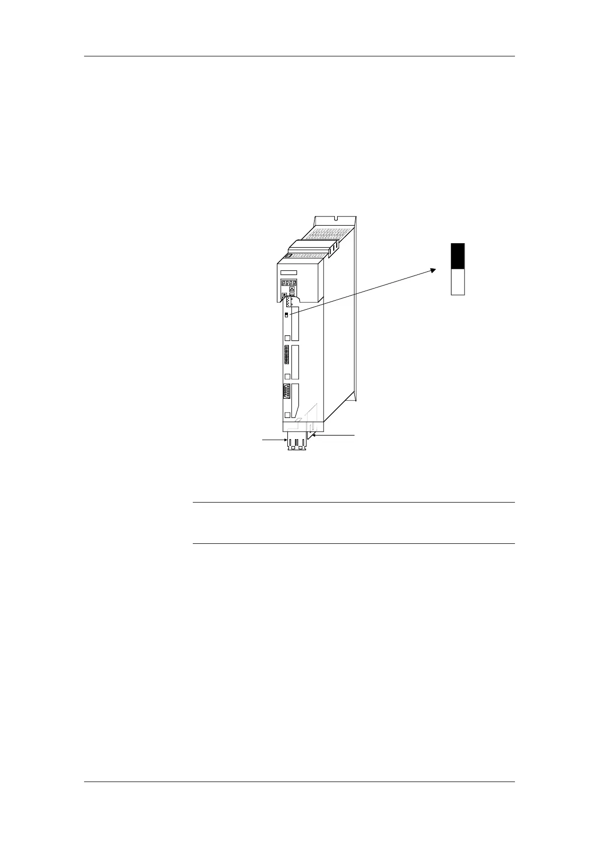
SIEMENS
X100
A
S1
BX101
CX103
Shield connection
for control cables
Shield connection
for motor cable
−
Compact PLUS
S1
ON
OFF
Switch for
bus termination
Fig. 8.1-13 S1 bus-terminating switches in the Compact PLUS type of unit
In the Compact and chassis type units, two mutually independent USS
interfaces (SCom1 and SCom2) are available. Switch S1 or S2 is
provided for switching in the terminating resistor.
If the bus-terminating node is a T100 board, the bus terminating
resistors are switched in through the two plug-in jumpers, X8 and X9.
NOTE
 Loading...


