02.2004 Communication / USS
Siemens AG 6SE7087-6QX70 (Version AD)
SIMOVERT MASTERDRIVES Compendium Motion Control 8.1-27
Equipotential bonding is necessary in order to prevent differences in
potential (e.g. due to different supply voltages) between the individual
bus nodes (converters and master system).
♦ This is achieved with the help of equipotential-bonding conductors:
• 16 mm
2
Cu for equipotential-bonding conductors up to 200 m in
length
• 25 mm
2
Cu for equipotential-bonding conductors more then
200 m in length
♦ The equipotential-bonding conductors are to be laid so that there is
the smallest possible surface area between a conductor and any
signal cables.
♦ The equipotential-bonding conductor must be connected to the earth
electrode/protective conductor through the largest possible surface
area.
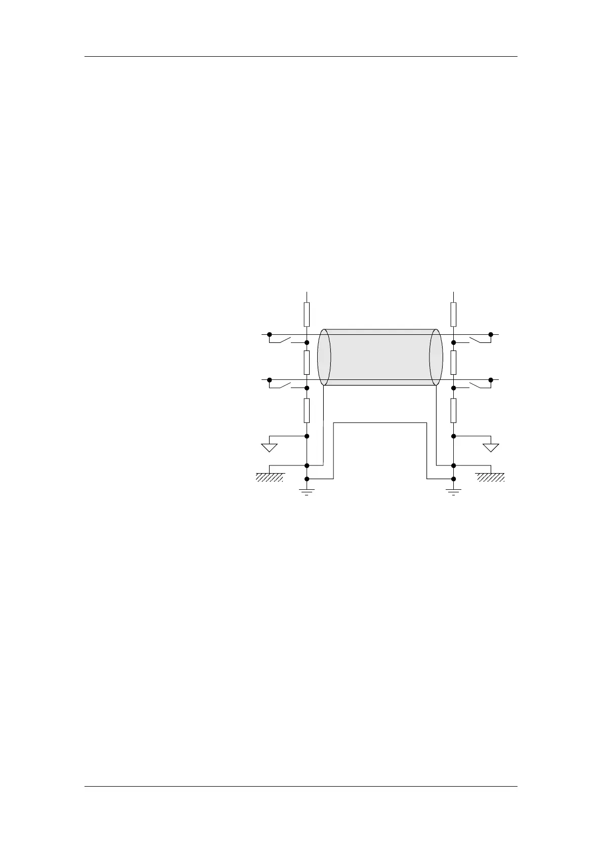
Housing earth
Shield bar
External 0 V
signal level
Bus termination
and
Basic network
Equipotential bonding
RS485 N
Sield
RS485 P
Data line
+ 5 V
390
220 220
+ 5 V
390 390
390
Fig. 8.1-12 Shielding and equipotential bonding
Instructions for laying cables:
♦ Bus cables (signal cables ) must not be laid close to and parallel to
power cables.
♦ Signal cables and the associated equipotential-bonding cables must
be laid as closely together as possible and kept as short as
possible.
♦ Power cables and signal cables must be laid in separate cable
ducts.
♦ Shields must be connected through the largest possible surface
area.
For more information on electromagnetically compatible installation of
systems, see for example Chapter 3 of the Compendium or the
description "Instructions for Design of Drives in Conformance with EMC
Regulations" (Order No. 6SE7087-6CX87-8CE0).
Equipotential
bonding
Laying cables
 Loading...


