Technology Option F01 08.2012
6SE7087-6QX70 (Version AN) Siemens AG
9-124 Compendium Motion Control SIMOVERT MASTERDRIVES
The application example contains the following configuration:
♦ 2 Siemens synchronous servo motors: 1FK6 with resolver and 1FT6
with optical sine/cosine encoder (only one motor required for
positioning)
♦ 2 MASTERDRIVES MC converters with technology option F01 (only
one converter required for positioning)
♦ Both drives should be operated in the following modes:
• Homing (this is required for positioning, since resolvers and
optical encoders are incremental and not absolute encoders)
• Point-to-point positioning (MDI; axis type "rotary axis", i.e. without
fixed stops)
• Synchronization with 1:1 transmission ratio using the virtual
master axis and the SIMOLINK drive interface
♦ When the two-axis pack is used, the synchronization can be
checked with reference to an LED light beam, which is visible
through drilled holes in the flywheel mounted on the motor shafts
when the synchronization is operating correctly.
Acknowledge
ON/OFF
X101.
24V
.3
.4
.5
.6
.7
.8
.1
Resolver
SBR2
SLB
.3
.4
.5
.6
.7
.8
X101.
.1
24V
ERN Encoder
SBM
SLB
SIMOLINK
1FK6... 1FT6...
MASTERDRIVES MC
+10V
.9
.10
.11
Virtual
Master
Drive1
Slave
Drive 2
Master
Betriebsart
Homing MDI Synchronization
0 1 1
1 1 0
Homing MDI
Rough pulse
0=MDI-block 3
1=MDI-block 1
Homing
MDI + synchronization
Jog forwards Start
Switch assignment
for both drives
Digital
I/Os
Digital
I/Os
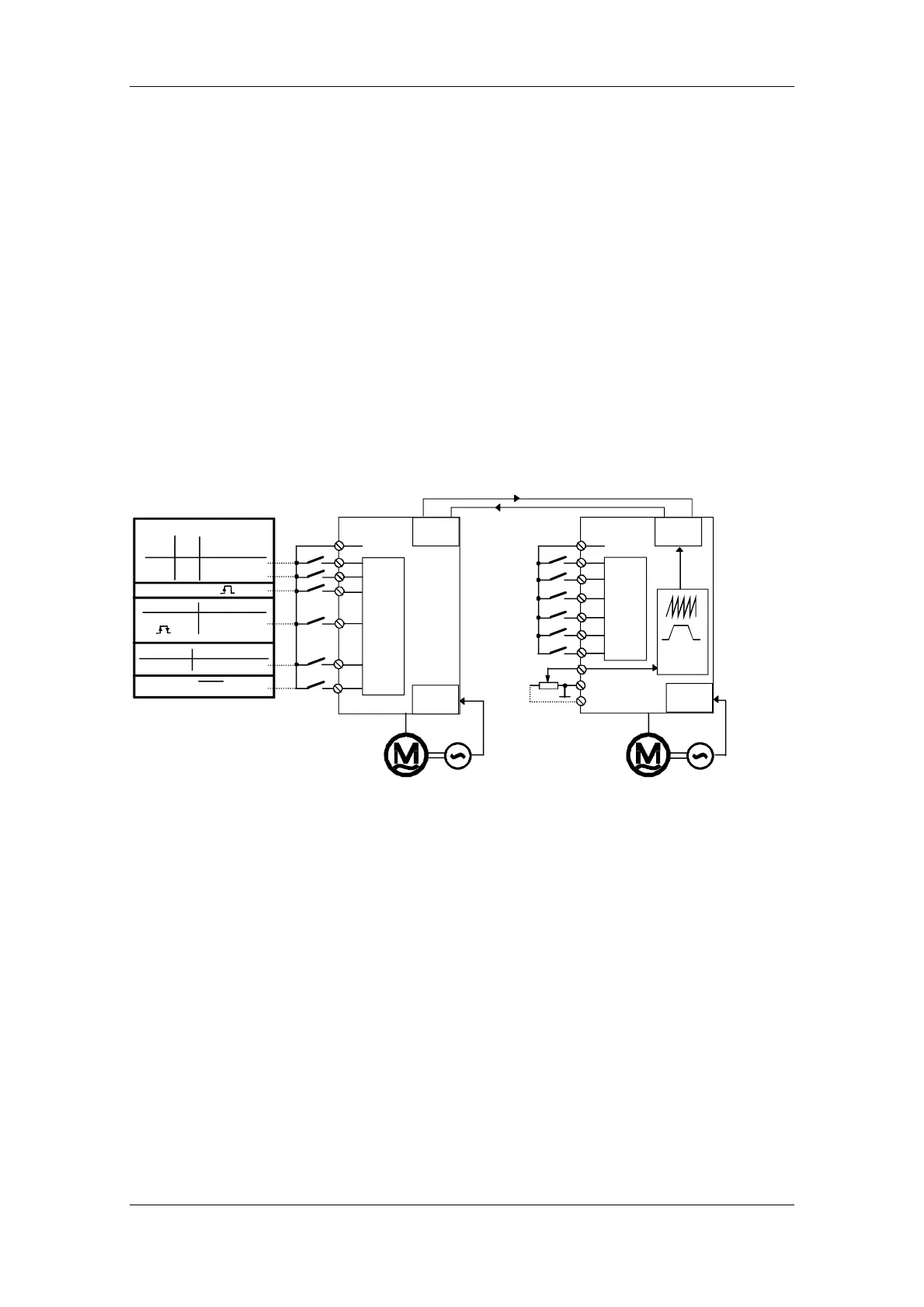
Fig. 9-46 Application example 2: hardware configuration and wiring
The application example guides you through the relevant pages of the
function diagram and the parameter settings. It is assumed that the
basic units have been started up in speed control mode, as described
in Chapter 6. If you only want to use the positioning functions, you need
only one drive instead of two for the self-study and you can skip the
sections starting from 9.7.10.
9.7.2.2 Overview diagram
The overview diagram in Fig. 9-47 shows how the technology functions
are interconnected.
 Loading...


