Communication / PROFIBUS 09.2008
6SE7087-6QX70 (Version AK) Siemens AG
8.2-106 Compendium Motion Control SIMOVERT MASTERDRIVES
8.2.9.7 Communication interface
P918: Node address
Value range 0 – 125 (126 is reserved for start-up purposes)
The node addresses 0, 1 and 2 are generally occupied by master
and configuration tools and therefore should not be used for
slaves on the PROFIBUS. Address 3 is the first appropriate node
address to be used for a slave on the PROFIBUS.
8.2.9.8 Clock synchronous application
Course of an isochronous DP cycle
Example (simplest DP cycle, standard case for MASTERDRIVES)
Master
DP cycle
Speed/current
controller clock
time
T
SAPC
Slave 1...3
ReserveT S1 S2 S3
MSG
T ReserveS1 S2 S3
MSG
T ReserveS1 S2 S3
MSG
T ReserveS1 S2 S3
MSG
T
R1 R2 R3 R1 R2 R3 R1 R2 R3 R1 R2 R3
R1 R1 R1 R1 R1 R1 R1 R1 R1 R1 R1 R1 R1 R1 R1 R1 R1
T
I
= 0 T
O
= 0
Pos Controller
clock time
(T
MAPC
)
T
M
= 0
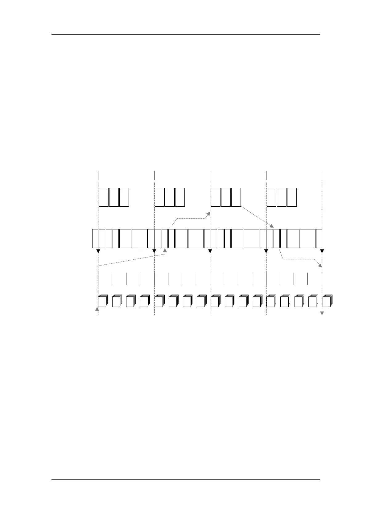
Fig. 8.2-37 Example: simplest DP cycle
In this example four DP cycles are needed for a response in the position
control circuit.
♦ 1. Actual value recording (in slave)
♦ 2. Actual value transmission (slave -> master)
♦ 3. Position controller (in master)
♦ 4. Setpoint transmission (master -> slave)
This model makes few demands on the computing output of the master,
but leads to an increase in the control-specific dead time:
Dead time = 4 * T
DP
.
Node address
 Loading...


