08.2012 Technology Option F01
Siemens AG 6SE7087-6QX70 (Version AN)
SIMOVERT MASTERDRIVES Compendium Motion Control 9-19
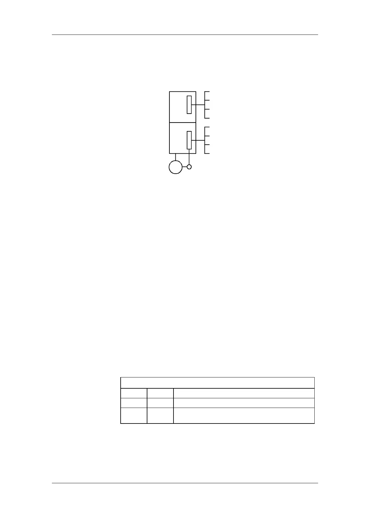
The following equipment variants of the MASTERDRIVES MC with
encoder evaluation boards ("Sensor boards") are possible. A maximum
of 2 encoders can be evaluated simultaneously in these configurations:
Motor encoder
in slot C
External encoder
in any slot
Sin/cos-encoder [SBM2]
EQN multiturn encoder [SBM2]
Pulse encoder [SBP]
SSI encoder [SBM2]
Resolver [SBR1/SBR2]
Sin/cos-encoder [SBM2]
Multiturn encoder [SBM2]
Pulse encoder [SBP]
M
3~
(for asynchronous motors only)
Fig. 9-10 Overview of suitable sensor boards
9.4.4 Resolver evaluation [230]
The resolver operates with an analog inductive measuring system. The
resolution of the analog signals is 4096 increments per revolution. The
positioning accuracy of the resolver that can be achieved under
practical conditions is limited to approximately 1000 steps per motor
revolution.
The two-pole resolver measures the absolute position of the rotor from
0° to 360°. In multi-pole resolvers, the measured position is not
assigned to a unique mechanical rotor position.
Sensor boards SBR1 and SBR2 are available (with/without pulse
encoder simulation) for the evaluation of resolver signals [230].
Cable lengths of up to 150 m can be used for the two-pole resolver.
Attention should be paid to proper EMC installation (screening, physical
separation of the power cables). Please also keep in mind that –
irrespective of the type of converter, pulse frequency and type of power
cable between motor and converter – the permissible power cable
length can be less than150 m.
This parameter is automatically initialized with the value 1 (= two-pole
resolver) when sensor board SBR1 or SBR2 is used. The setting must
be changed for multi-pole resolvers.
Select Motor Encoder
Par. Value
Meaning
P130 1
2-pole resolver as motor encoder
P130 2
Resolver with motor pole pair number as motor
encoder
Principle
Cable length
Select motor
encoder P130
 Loading...


