Communication / USS 02.2004
6SE7087-6QX70 (Version AD) Siemens AG
8.1-24 Compendium Motion Control SIMOVERT MASTERDRIVES
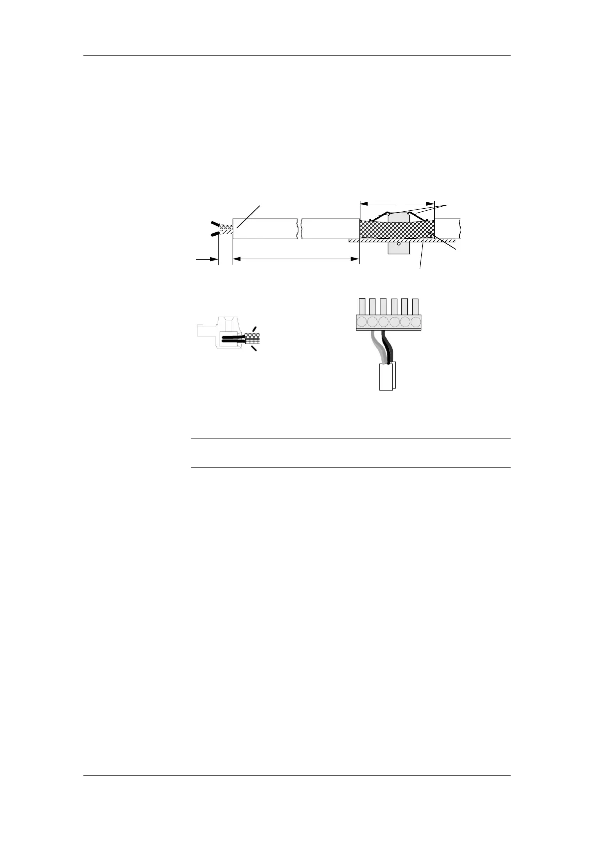
8.1.4.2 Fitting the bus cable
At all interfaces to the CUPM, CUMC, CUVC control electronics, the
SCB2 board and the T100, except for connectors X103 and X300 or
X448 (9-pin SUB-D connectors), the USS bus cable is connected by
means of screw/plug-in terminals. The correct method of connecting the
bus cable at the connector is shown in the following diagram.
Removing
the bus connector
without
interrupting the bus
The shield must not be exposed here!
Do not bend
the spring
excessively!
35
Shield
Modify the length
according to the type of unit
Connector
Example of 2 copper cores
in a screw terminal
Converter housing
Bus cable 1
Bus cable 2
15 mm
Fig. 8.1-9 Connecting up the bus cables
It must be ensured that both copper cores are securely held inside the
screw terminal.
NOTE
 Loading...


