09.2008 Communication / PROFIBUS
Siemens AG 6SE7087-6QX70 (Version AK)
SIMOVERT MASTERDRIVES Compendium Motion Control 8.2-47
8.2.6 Connecting up the CBP to the PROFIBUS
8.2.6.1 Assignment of plug-in connector X448
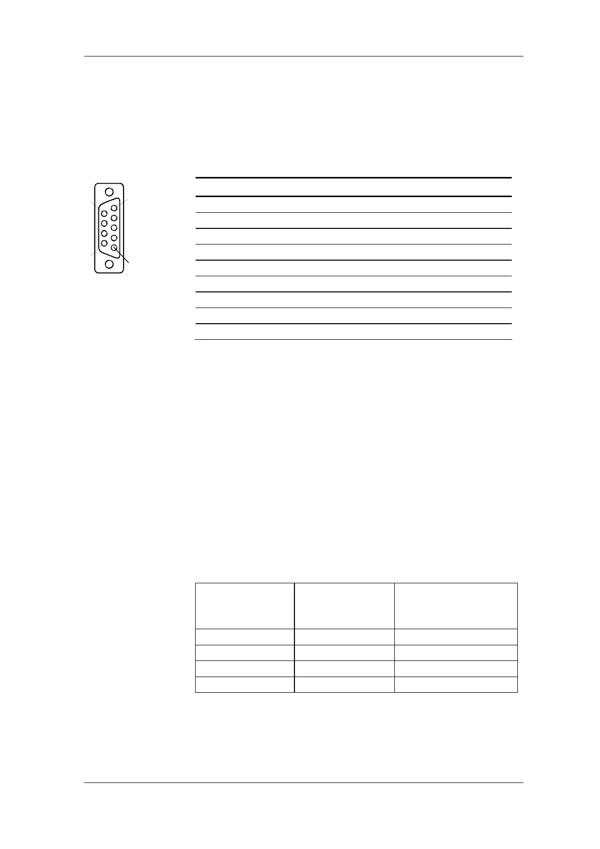
The CBP optional board has a 9-pin Sub-D socket (X448) which is
provided for connecting the CBP to the PROFIBUS system. The
connections are short-circuit proof and floating.
Pin Designation Significance Area
1 SHIELD Ground connection
2 - Not connected
3 RxD/TxD-P Receive/transmit data P (B/B´) RS485
4 CNTR-P Control signal TTL
5 DGND PROFIBUS data reference potential (C/C´)
6 VP Power supply Plus 5 V ± 10 %
7 - Not connected
8 RxD/TxD-N Receive/transmit data N (A/A´) RS485
9 - Reference filtered M_EXT
Table 8.2-9 Pin assignment of X448 connection
8.2.6.2 Connecting up the bus cable by means of the RS485 bus connecting
system
With the PROFIBUS, data transfer according to RS485 is most frequently
used. A twisted, shielded copper cable with one pair of wires is used.
Up to a maximum of 124 units can be connected to a PROFIBUS phase.
In one bus segment, up to 32 units can be connected together in a linear
structure. If there are more than 32 nodes, repeaters (power amplifiers)
must be used in order to link up the individual bus segments.
The maximum cable length depends on the baud rate (transmission
speed).
The maximum cable length can be increased by using repeaters but no
more than three repeaters may be connected in series.
The maximum cable lengths given in the following table can only be
ensured if PROFIBUS bus cables are used (e.g. Siemens PROFIBUS-
cable with MRPD 6XV 1830-0AH10).
Baud rate Max. cable length in
a segment
Max. distance between 2
stations
[m] [m]
9.6 to 187.5 kbaud 1000 10000
500 kbaud 400 4000
1.5 Mbaud 200 2000
3 to 12 Mbaud 100 1000
Table 8.2-10 Permissible cable length of a segment with RS485 repeaters
Connecting up
1
5
6
9
Maximum cable
lengths
 Loading...


