Instructions for Design of Drives in Conformance with EMC Regulations 05.2003
6SE7087-6QX70 (Version AD) Siemens AG
3-4 Compendium Motion Control SIMOVERT MASTERDRIVES
3.3 The frequency converter and its electromagnetic
compatibility
3.3.1 The frequency converter as a noise source
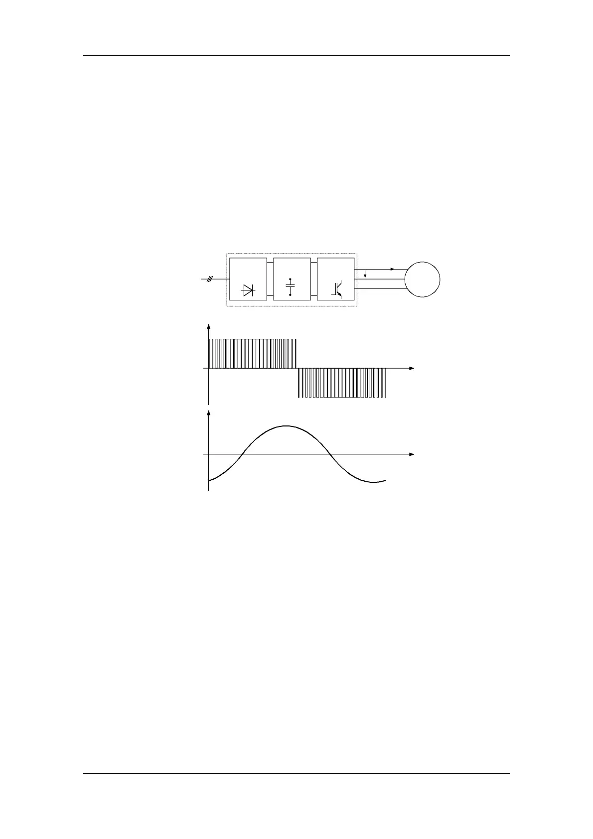
SIMOVERT MASTERDRIVES frequency converters operate with a
voltage-source DC link.
In order to keep the power losses as low as possible, the inverter
switches the DC link voltage to the motor winding in the form of voltage
blocks.
An almost sinusoidal current flows in the motor.
M
3~
I
U
Mains
Frequency converter
Motor
U
t
I
Inverter
DC
link
Rectifier
t
Fig. 3-1 Block diagram showing output voltage V and motor current I of a frequency
converter
The described mode of operation in conjunction with high-performance
semiconductor switching elements have made it possible to develop
compact frequency converters which now play a vital role in drive
technology.
As well as having many advantages, the fast semiconductor switches
also have one disadvantage:
A pulse-type noise current flows to ground through parasitic
capacitances C
P
at each switching edge. Parasitic capacitances exist
between the motor cable and ground, and also within the motor.
Mode of operation
of SIMOVERT
MASTERDRIVES