Configuration and Connection Examples 12.2010
6SE7087-6QX70 (Version AM) Siemens AG
2-24 Compendium Motion Control SIMOVERT MASTERDRIVES
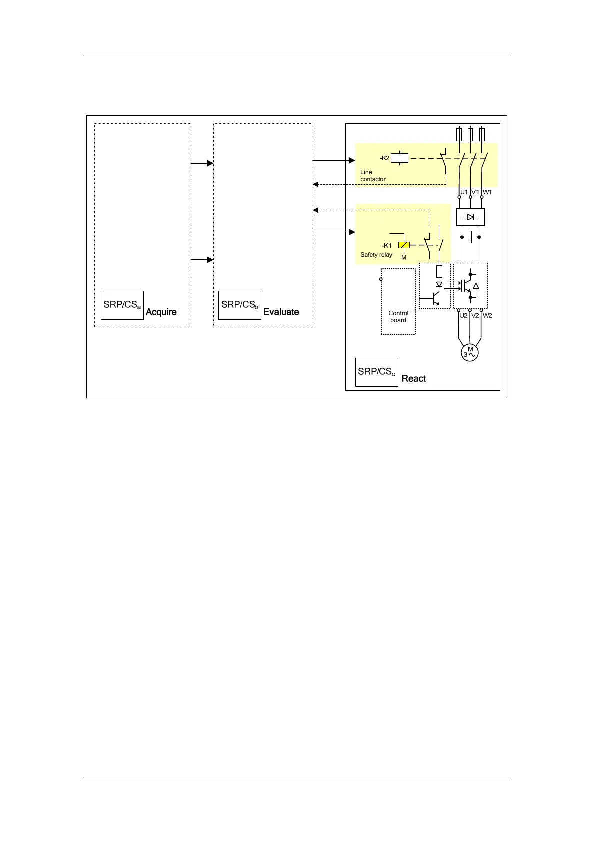
2.4.4.1 STO principle in a safety function
Fig. 2-9 STO principle, two-channel structure
A safety function basically comprises the subsystems:
ACQUIRE, EVALUATE and REACT.
Every safety function must be constructed of appropriate sensors, logic
units and actuators.
The subsystems ACQUIRE and EVALUATE are not examined in detail
here. The components must be selected and designed according to the
requirements of the safety function to be implemented.
The subsystem REACT is in principle a two-channel structure. The first
channel contains the safety relay –K1 of the drive (option K80). This
operates according to the principle of pulse disconnection with
monitoring.
The second channel is formed by the line contactor –K2 which must be
connected into the mains feeder cable. The line contactor is monitored
by the positively driven NC contact.
As an alternative to integrating the line contactor, it is also possible to
use one motor contactor for each motor as a second safety channel.
The calculation results for the example applications below can be
applied analogously.