Communication / USS 02.2004
6SE7087-6QX70 (Version AD) Siemens AG
8.1-30 Compendium Motion Control SIMOVERT MASTERDRIVES
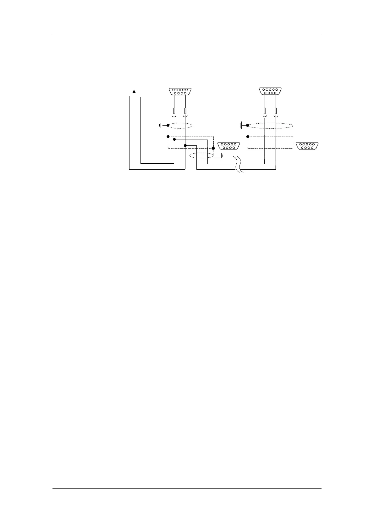
The following illustration shows the structure of a bus connection via
the 9-pin connector, X103 (Compact PLUS).
RS485 P
RS485 N
No bus termination
Switch S1 "OFF"
At the last node on the bus cable,
switch S1 must be in the "ON" position.
RS485 N RS485 P RS485 N RS485 P
To the master
9-pole Sub-D 9-pole Sub-D
9-pole Sub-D
9-pole Sub-D
X103 X103
8 3 8 3
Fig. 8.1-15 Connection of the 2-wire bus cable at terminal strip X103
(Compact PLUS)
Bus connection via
connector X103
 Loading...


