Communication / PROFIBUS 09.2008
6SE7087-6QX70 (Version AK) Siemens AG
8.2-50 Compendium Motion Control SIMOVERT MASTERDRIVES
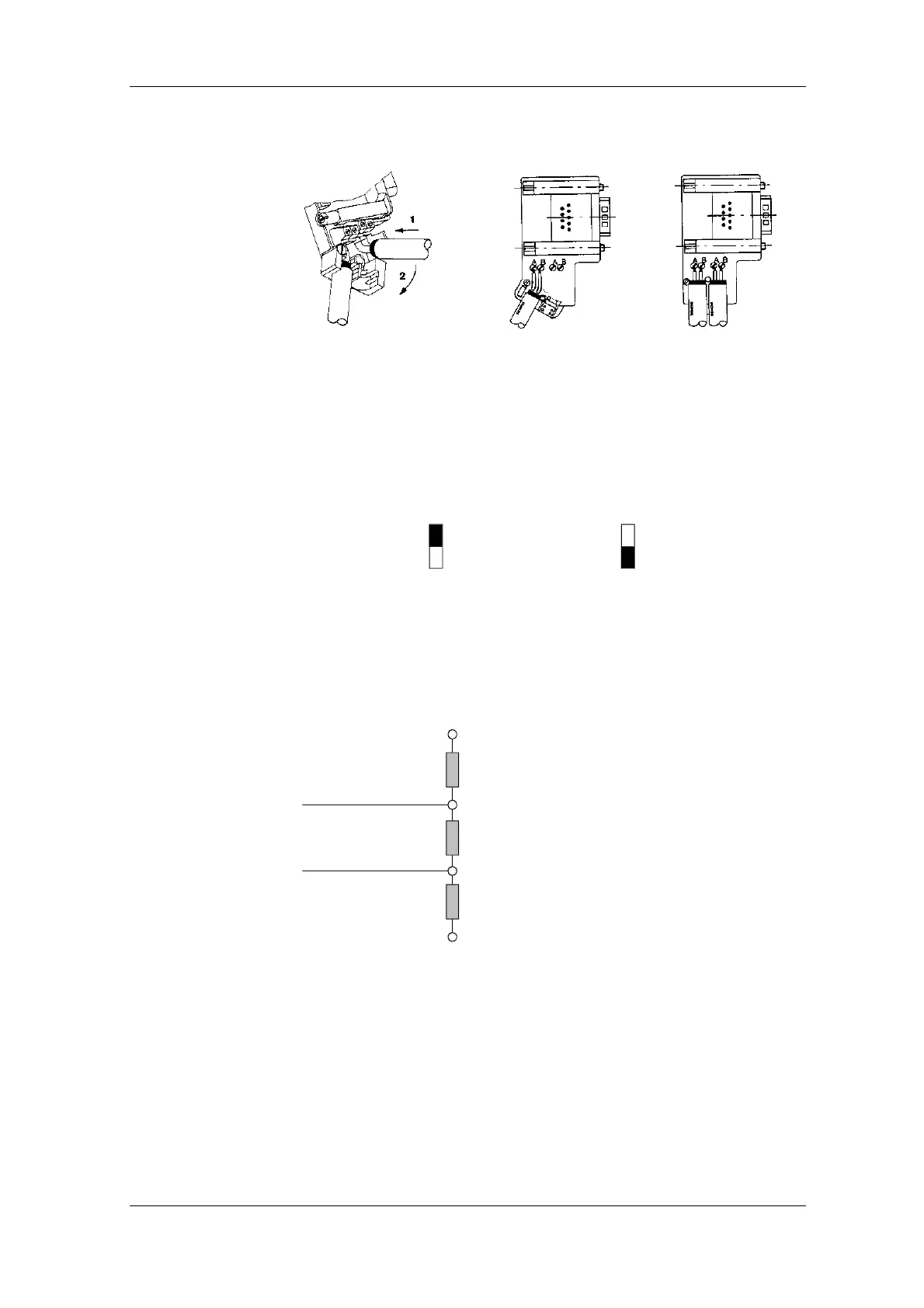
Bus cable connection for first
and last nodes on the bus
1
Bus cable connection for
other nodes on the bus
1
The bus cable must be connected on the left!
Fig. 8.2-11 Connecting up the bus cable to the bus connector
Each bus segment must be fitted with a resistor network, the bus
termination, at each end.
If the recommended bus connectors can be used, the bus termination
can be connected or disconnected by means of switches.
on
off
on
off
Terminating resistor
connected
Terminating resistor
not
connected
Fig. 8.2-12 Switch positions for connected or disconnected bus termination resistor
If these bus connectors are not used, the user must ensure installation of
a bus termination network at the first and last bus station in accordance
with the following illustration.
Data line
Data line
VP (PIN 6)
390 Ohm
RxD/TxD-P (PIN 3)
220 Ohm
RxD/TxD-N (PIN 8)
390 Ohm
DGND (PIN 5)
Fig. 8.2-13 Bus termination network
Installing the bus
cable
Bus termination
 Loading...


