12.2010 Communication / SIMOLINK
Siemens AG 6SE7087-6QX70 (Version AM)
SIMOVERT MASTERDRIVES Compendium Motion Control 8.3-23
• The time slot T
0
= 1/pulse frequency is set on MASTERDRIVES
units by selecting the pulse frequency (P340). Thus the following
applies for the selection of the bus cycle time:
Bus cycle time = 2
n
x slowest time slot to be synchronized;
where n ∈ N = {2, 3, ...}
Example:
If the position control loops of the various converters have to be
synchronized to each other, the selected bus cycle time has to be
an n-fold quantity of 4 T
0
.
Transceiver (slave drive 2) is given the node address 1 and transceiver
(slave drive 3) is given the node address 2.
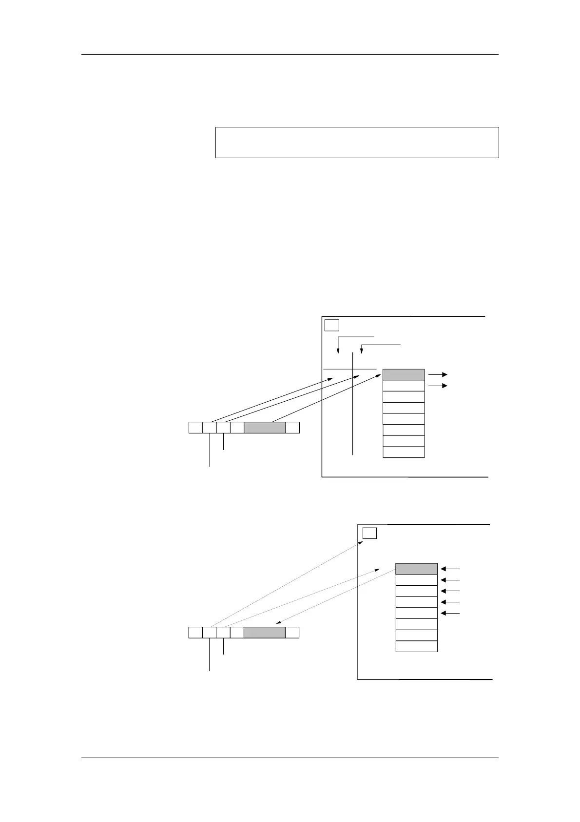
The following diagrams show the assignment of the process data to be
read or written using the example of master drive 1 and slave drive 2.
SLB in master drive (dispatcher)
0
ZW_21
Address
Channel number
0
Node address
Telegram
from which address to be read
from which channel number
to be read
ZW_3
Receive memory (8 x 32 bit)
0
0
Process data
1
2
Address
Channel
number
ZW_2
ZW = Status word
SIMOLINK
Fig. 8.3-8 Master drive 1, reading data
SLB in master drive (dispatcher)
0
STW_2
0
Address
Channel number
0
Node address
Telegram
STW_3
s
set
n
set
a
set
8 channels 32 bit each
0
1
2
3
4
5
6
7
Process data
STW_2
STW = control word
SIMOLINK
Fig. 8.3-9 Master drive 1, writing data
Parameterization of
the transceivers
Parameterization of
process data
monitoring
 Loading...


