Communication / CBC 03.2010
6SE7087-6QX70 (Version AL) Siemens AG
8.4-12 Compendium Motion Control SIMOVERT MASTERDRIVES
35
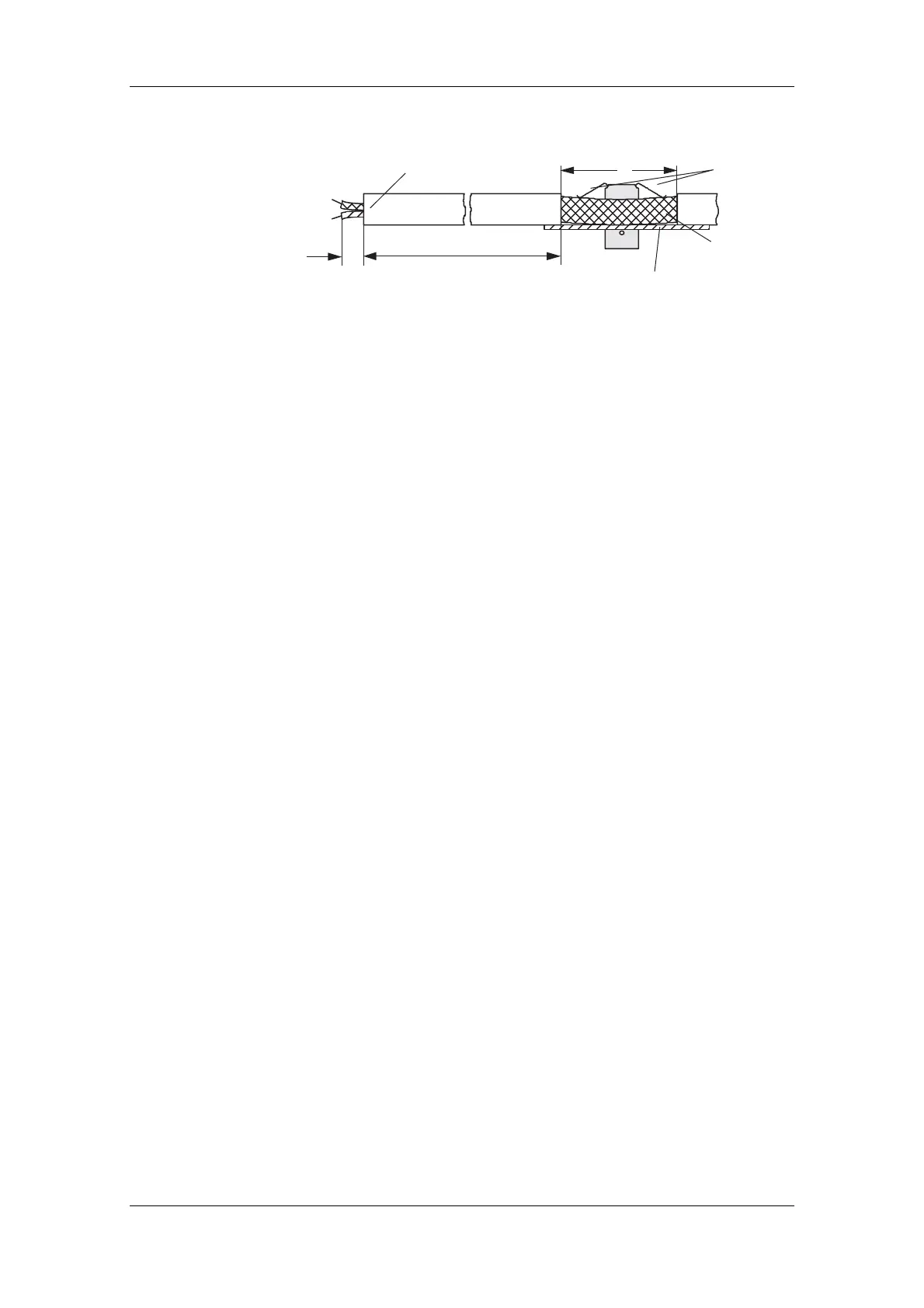
15 mm
The shield must not
be exposed here!
Adapt length to match
type of construction!
Converter housing
Shield
Do not excessively
bend springs!
Fig. 8.4-11 Removing insulation from the cable when shield clamps are used
♦ Please avoid differences in potential (e.g. as a result of different
power supply levels) between the converters and the PROFIBUS-
DP master.
♦ Use equipotential bonding cables:
• 16 mm
2
Cu equipotential bonding cables up to 200 m
• 25 mm
2
Cu equipotential bonding cables over 200 m
♦ Route the equipotential bonding cables so that there is the smallest
possible surface between the equipotential bonding cables and
signal cables.
♦ Connect equipotential bonding cables to the ground/protective
conductor through the largest possible surface area.
Please comply with the following instructions when laying cables:
♦ Do not lay bus cables (signal cables) directly parallel to power
cables.
♦ Lay signal cables and the associated equipotential bonding cables
with the lowest possible distance between them and on the shortest
routes.
♦ Lay power cables and signal cables in separate cable ducts.
♦ Attach shields through a large surface area.
Potential
equalization
Laying cables
 Loading...


