02.2004 Communication / CBC CANopen Communication Board
Siemens AG 6SE7087-6QX70 (Version AD)
SIMOVERT MASTERDRIVES Compendium Motion Control 8.5-75
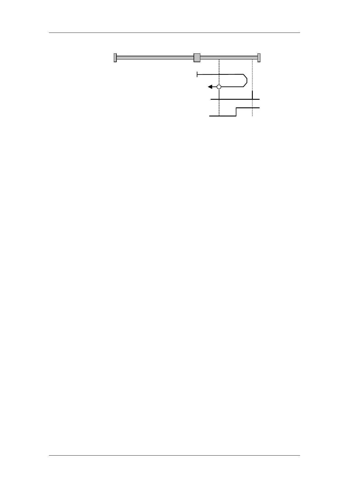
Positive Limit Switch
Index Pulse
2
Fig. 8.5-5 Homing_method 2
The axis is positioned to the left of the Bero installed as a limit switch.
The homing operation is started by bit 4 in the control word.
The axis traverses under speed control at homing approach velocity v
A
[MD7] towards the Bero. When the Bero responds, the axis decelerates
down to homing creep velocity v
R
[MD6] and reverses its direction of
rotation. When it exits the Bero in the negative direction, it searches for
the next zero pulse of the position encoder. When the zero pulse is
found, the axis is braked to a standstill under speed control. It retraces
the deceleration path traveled as a result of the braking operation by
executing a position-controlled return motion (positioning) towards the
zero pulse. The axis then activates "Homing Attained" in the status
word via bit ARFD.
Homing_method 2
 Loading...


