Configuration and Connection Examples 12.2010
6SE7087-6QX70 (Version AM) Siemens AG
2-52 Compendium Motion Control SIMOVERT MASTERDRIVES
The subsystem EVALUATE of the supplementary safety function
Emergency Stop consists here of three SIRIUS 3TK3842 safety
switching devices. The safety switching devices feature instantaneous
and time-delayed enabling circuits.
The safety switching device –A1 is used to evaluate the Emergency
Stop button. The devices –A2 and –A3 provide a safe time delay for
switch-off and are energized by –A1 in each case via the cascading
input terminal 1.
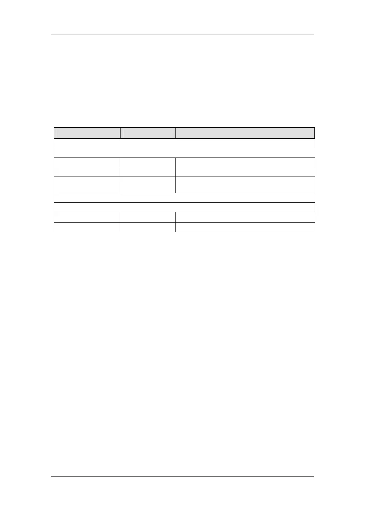
Parameter Value Comment
Safety switching devices 3TK2842 –A1, –A2 and –A3
PFH
d
5.4 x 10
-11
/ h Specified by manufacturer
Service life T1 = 20 years Specified by manufacturer
Performance Level PLe
No distinction between instantaneous and time-
delayed enabling circuits
Result
PFH
d
1.62 x 10
-10
/ h
)3A( PFHd)2A( PFHd)1A( PFHdPFHd −+−+−=
Performance Level PLe
When the Emergency Stop button is actuated, the voltage supply to the
line contactor –K2 and the safety relay –K1 is disconnected via the
time-delayed output (28) of –A1. The contactor relays –K3 and –K4
therefore have no influence on the proper functioning of –K1 and –K2
when an Emergency Stop is requested.
The component –K1 is tested every time –A2 starts via –K3. The
contactor –K2 is tested every time –A1 starts.
Accumulation of faults in channel 2 between two consecutive actuations
of the Emergency Stop button is not detected.
♦ The structure conforms to fundamental and proven safety principles
and the requirements of Category B. Protective circuits are
provided.
♦ The safety function always remains operative when a component
fails. Component failure is detected.
This structure corresponds to Category 3 in accordance with EN ISO
13849-1:2008 /R3/.
Subsystem
EVALUATE
Subsystem REACT
 Loading...


