Technology Option F01 08.2012
6SE7087-6QX70 (Version AN) Siemens AG
9-128 Compendium Motion Control SIMOVERT MASTERDRIVES
♦ In MDI mode, terminal 6 is used to switch between MDI block 1 (low
signal) and 3 (high signal). This selection is made via bit 9 of the
positioning control word [809], which is connected to the MDI mode
[823] and switches there between the permanent NC blocks
configured in U550 and U552.
Bit 8 of the positioning control word is initialized permanently to "1":
U710.10=16 ; MDI block selection [MDI_NO] from terminal X101.6
U710.09=1 ; [90] ==> [809]
Terminals 3 and 4 select the mode according to the following truth
table:
Signal at
Terminal 3
Signal at
Terminal 4
Mode Bitmap at
[MODE_IN] [809.4]
2
3
2
2
2
1
2
0
0 0 - -
1 0 11 = Synchronization 1 0 1 1
0 1 2 = Homing 0 0 1 0
1 1 3 = MDI 0 0 1 1
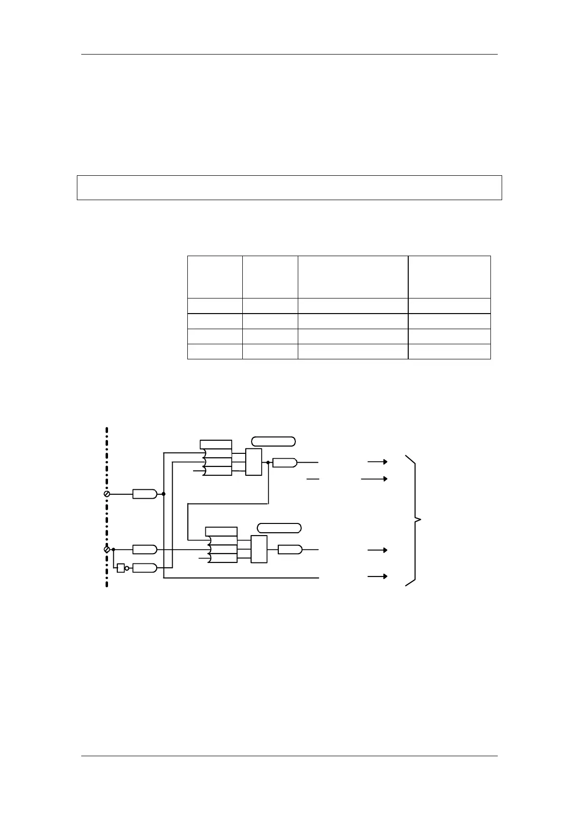
The small logic circuit below generates the required mode selection bits
28...31 [MODE_IN] for the positioning control word [809] from the
signals at terminals 3 and 4:
&
U221 (0)
B010
B013
B001
.01
.03
.02
B601
³
1
U239 (0)
B601
B012
B000
.01
.03
.02
B619
U950.78=4
U950.90=4
B0010
DIN 1
B0012
DIN 2
1
B0013
1
0
0
U710.32=601
[Sheet 765]
Basic unit [Sheet 90]
[Sheet 809]
U710.31=0
U710.30=619
U710.29=10
2
3
2
2
2
1
2
0
MODE_IN
(Mode selection)
X101.3
X101.4
Fig. 9-48 Application example 2: circuit for generating the modes
 Loading...


