05.2003 Instructions for Design of Drives in Conformance with EMC Regulations
Siemens AG 6SE7087-6QX70 (Version AD)
SIMOVERT MASTERDRIVES Compendium Motion Control 3-9
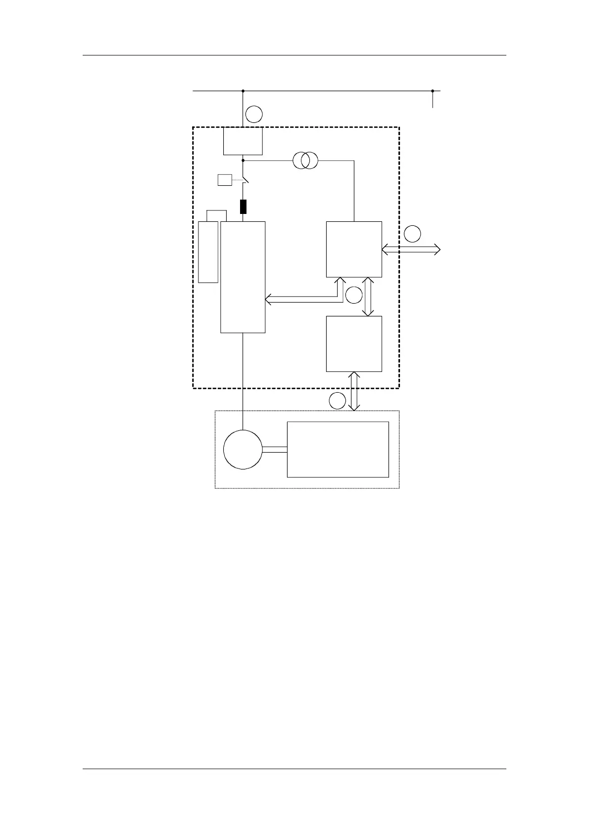
Filter
Frequency
converter
Control
e.g. Simatic
Mains
Sensors
(e.g. temp.,
position,
pressure)
Mechanical system
Machine
Cabinet
Line reactor
Braking unit
M
3~
3
2
4
1
Fig. 3-7 Block diagram of a drive system
The purpose of a frequency converter is to drive a motor. The
frequency converter, the relevant open-loop control and sensor system
are accommodated in a cabinet. The emitted noise has to be limited at
the mains connection point and therefore radio interference
suppression filters and line reactors are installed in the cabinet.
Assuming that all requirements are met at Point c - can it be supposed
that electromagnetic compatibility exists?
This question cannot just be answered with "yes" because EMC has to
be reliably ensured inside the cabinet as well. It is possible that the
control system produces electromagnetic influences at interfaces d
and f, and the sensor system at interfaces d and e.
Therefore, a radio interference suppression filter by itself cannot ensure
EMC!
See the following sections.
 Loading...


