05.2003 Instructions for Design of Drives in Conformance with EMC Regulations
Siemens AG 6SE7087-6QX70 (Version AD)
SIMOVERT MASTERDRIVES Compendium Motion Control 3-11
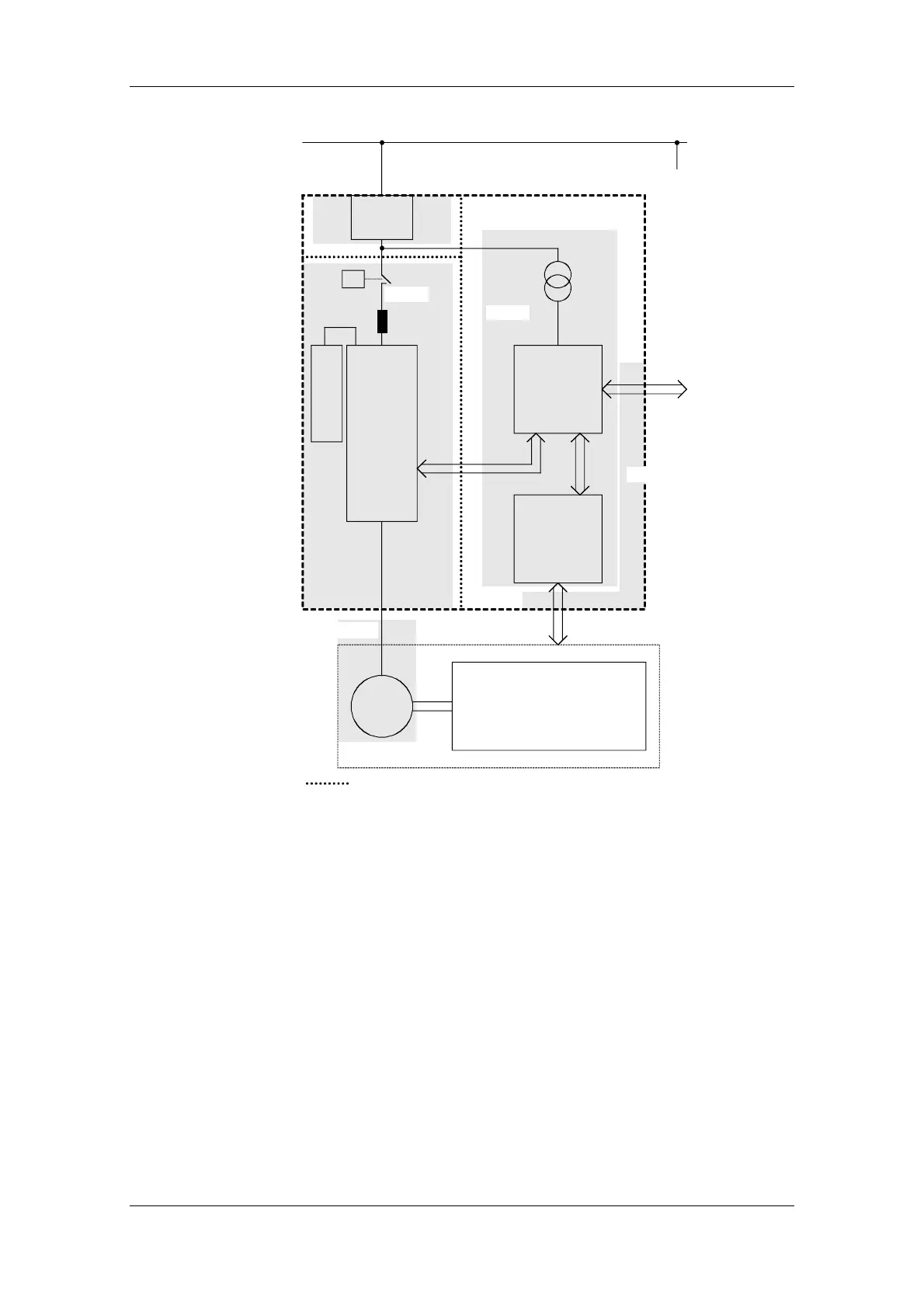
Filter
Frequency
converter
Control,
e.g. Simatic
M
3~
Mains
Sensors
(e.g. temp.,
position,
pressure)
Mechanical system
Machine
Cabinet
Braking unit
Zone A
Grounded
artition recommended
Zone B
Zone C
Zone D
Zone E
Fig. 3-8 Sub-dividing a drive system into zones
♦ Zone A is the cabinet connection to the line supply including filter.
The emitted noise should be kept at specific limit values here.
♦ Zone B contains the line reactor and the noise sources: frequency
converter, braking unit, contactor.
♦ Zone C accommodates the control transformer and the noise
receivers: control and sensor system.
♦ Zone D forms the interface between the signal and control cables to
the periphery. A defined noise immunity level is required here.
♦ Zone E comprises the three-phase motor and the motor supply
cable.
♦ The zones should be spatially separated in order to achieve
electromagnetic de-coupling.
 Loading...


