Function diagram
87654321
fp_mc_230_e.vsd
Encoder
MASTERDRIVES MC
08.09.04
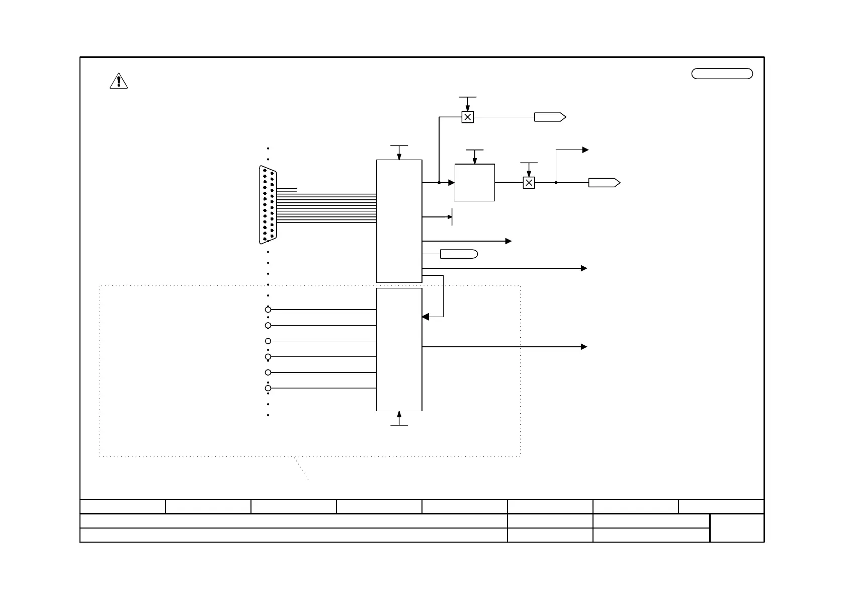
Resolver evaluation, motor encoder (SBR1/2 in slot C)
-230 -
V2.5
PTC / KTY
(see "Actual values" sheet
[491])
Pin assignment -X414:
3:SIN+
4:SIN-
5 : Internal shield for 3+4
6:COS+
7:COS-
8 : Internal shield for 6+7
9:+V
ss
11 : -V
ss
13 : +Temp
24 : Internal shield for 13+25
25 : -Temp
-X414
Resolver
evaluation
and excitation
Adjustment
F051 Encoder fault
A018 Encoder adjustment alarm
Pulse
encoder
simulation
(only with
SBR2)
<1>
P134:
0:512 pulses/revolution
1:1024 pulses/revolution
Zero pulse-
Track B-
Track B+
Track A-
Track A+
Zero pulse+
-X410/90
-X410/91
-X410/92
-X410/93
-X410/94
-X410/95
Non-floating
differential outputs
Pulse encoder
simulation
RS 422 standard
only for SBR2
to internal further
processing in an SBP
P130 = 1
P130 = 2
<1> The number of pulses per revolution applies to
a 2-pole resolver. In the case of resolvers with
more poles, the number of pulses per revolution
is correspondingly higher.
For further processing,
see "Actual values" sheet [500a]
<2>
<2> Range of values = 0 ... 2
32
-1
for one motor revolution
Note:
The signals are not isolated from potential.
A frame connection to X101/2 must also be
made.
The encoder connection may neither be closed nor removed when live!
The converter must be de-energized (24 V electronics power supply disconnected and DC link
fully discharged)!
Angle Offset
-180.00°...+180.00°
P132 (0.00)
Eval. motor encoder
P130
KK0090
Theta(mech.)
Sin/Cos Res
r133.1 / .2
0/1
Sel Encod SBR2
P134 (1)
n959.30 = 0
B0070 MeasV valid
KK0096
Resolver angle
Sign of P116
Transmission ratio
P116.1...2
 Loading...


