Appendix
A.5 System rules, sampling times and DRIVE-CLiQ wiring
Commissioning with Startdrive
402 Commissioning Manual, 11/2017, 6SL3097-4AA10-0BP1
● The motor encoder or Sensor Module should be connected to the associated Motor
Module.
Connecting the motor encoder via DRIVE-CLiQ:
– Single Motor Module Booksize to terminal X202
– Double Motor Module Booksize motor X1 to terminal X202 and motor X2 to terminal
X203
● If possible, Sensor Modules of direct measuring systems should not be connected to the
DRIVE-CLiQ line of Motor Modules, but rather to free DRIVE-CLiQ sockets of the Control
Unit.
Note
This restriction does not apply to star
-type connections for the Motor Modules.
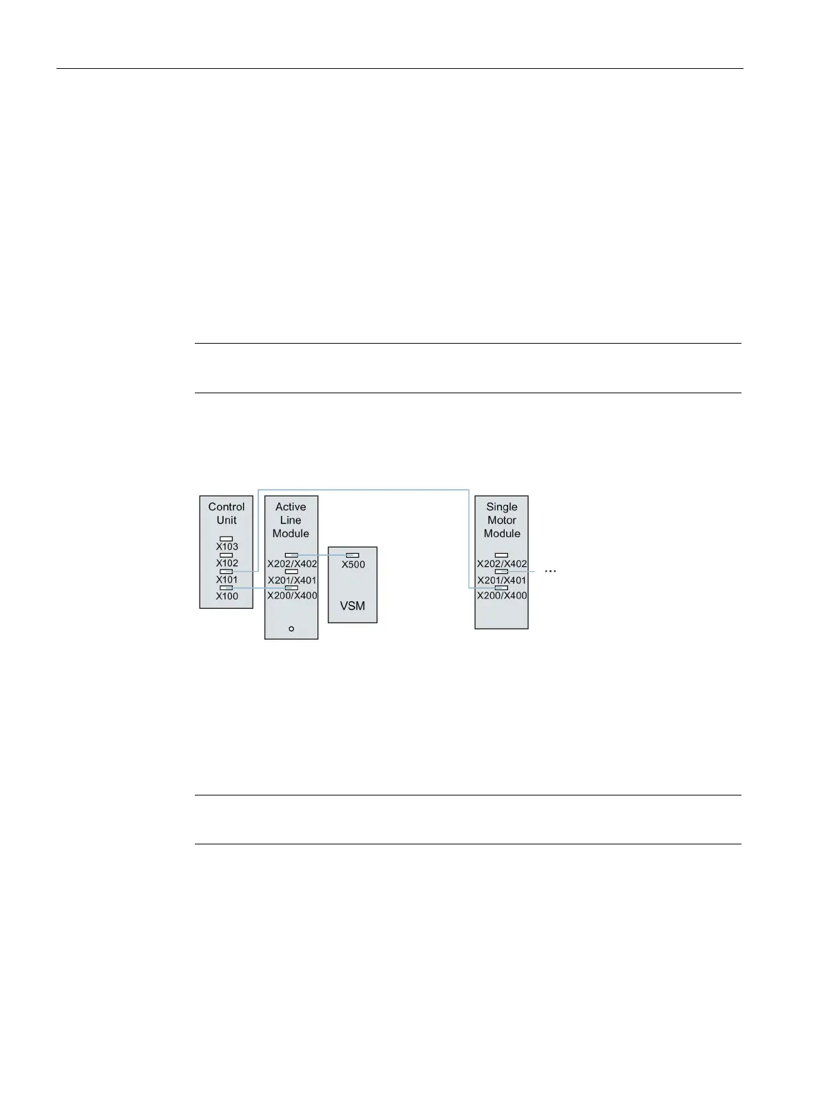
● When used for the infeed control, the Voltage Sensing Module (VSM) should be
connected to DRIVE-CLiQ socket X202 (booksize format) of the associated Line Module.
Figure A-1 Example of a topology with VSM for booksize components
● Terminal Modules should be connected to DRIVE-CLiQ socket X103 of the Control Unit in
series.
● If possible, Terminal Modules should not be connected to the DRIVE-CLiQ line of Motor
Modules, but rather to free DRIVE-CLiQ sockets of the Control Unit.
Note
This restriction does not apply to star
-type connections for the Motor Modules.

 Loading...


