Appendix
A.6 Overview of measuring systems / encoders
Commissioning with Startdrive
Commissioning Manual, 11/2017, 6SL3097-4AA10-0BP1
427
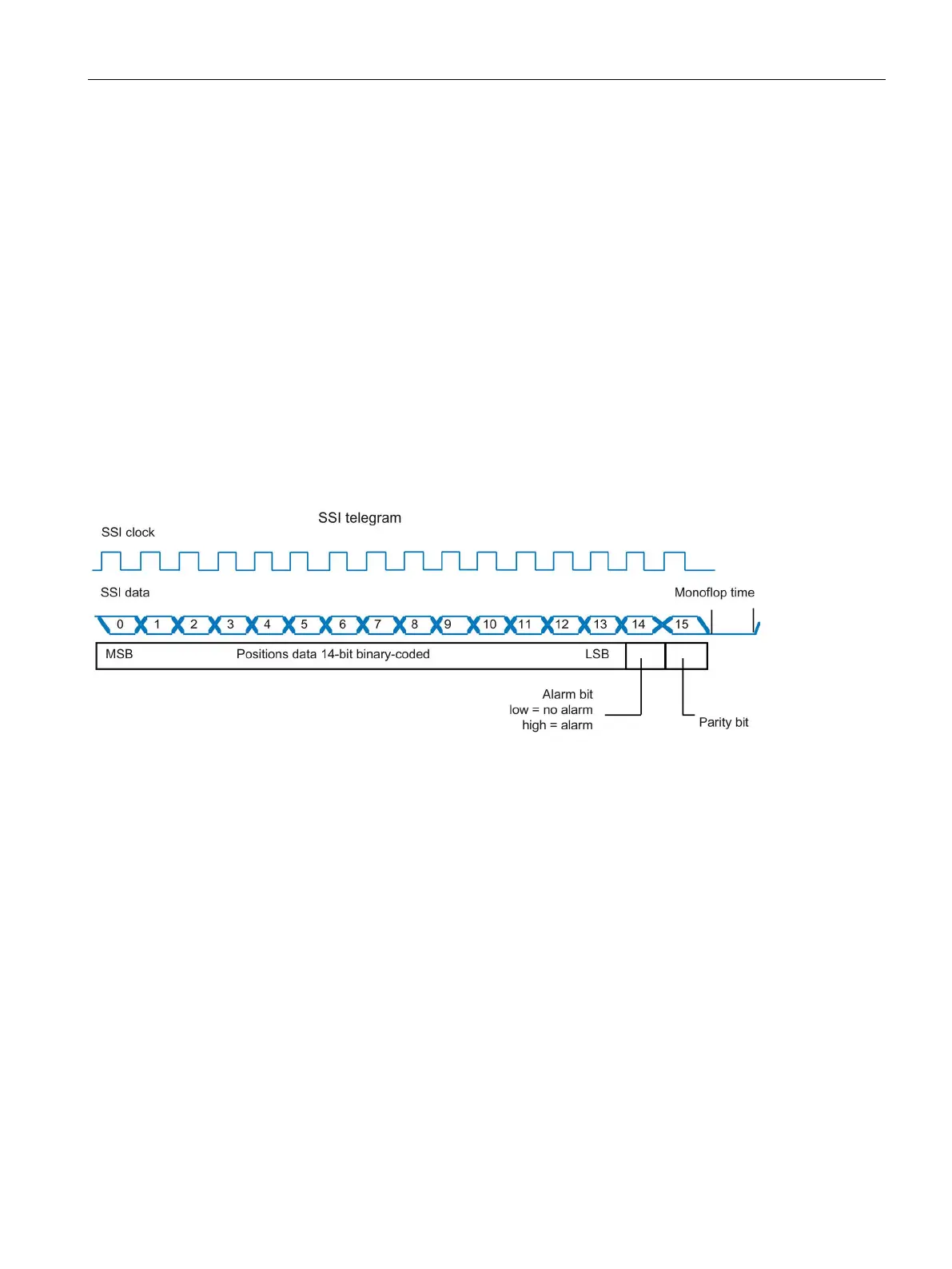
Parity bit - only when supported by the encoder
Another possibility to validate the transmission is to transfer a parity bit in the telegram. This
is a checksum over all bits of the telegram content. The following settings apply for the
parity: even (= low level) and odd (= high level). Refer to the data sheet to see whether the
encoder uses "even" or "odd" as checking criterion for the parity bit. With "even", a 1 is
automatically added when the number of bits is odd, so that the number becomes even. In
the case of an error, an odd number of bits is transferred.
The parity bit triggers a fault on the SINAMICS device (F3x110 bit 11, with x=1,2,3 for
encoder 1, 2, 3).
1. At "Bit activation", select the bit number for the parity bit.
2. At "Bit position", enter the position of the bit in the SSI protocol.
3. Under "Logic state", select whether the parity bit should be set for an even result or an
odd result.
Figure A-7 SSI encoder example telegram
The monoflop time describes the minimum wait time between two transfers of the absolute
value for the SSI encoder. The set value must be greater than or equal to the value specified
in the data sheet for the encoder.
1. Enter the monoflop time.
2. Select the signal level that the data line should have during the monoflop time:
– Low level
– High level

 Loading...


