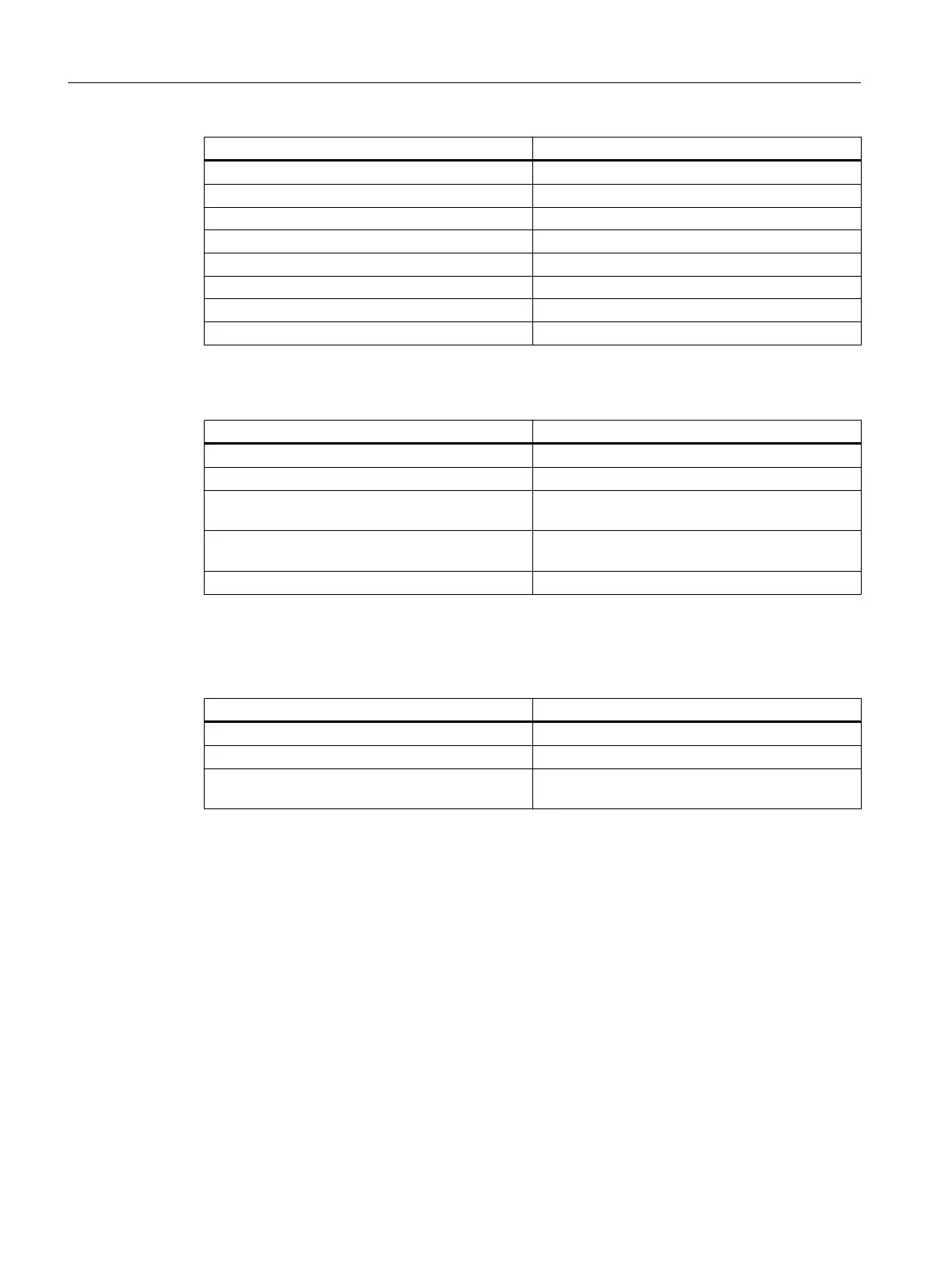
Template Description
feed_traverse_line_hori.fxw Horizontal line to illustrate the tool path during feed
feed_traverse_line_vert.fxw Vertical line to illustrate the tool path during feed
dimensioning_lines_hori.fxw Horizontal projection lines
dimensioning_lines_vert.fxw Vertical projection lines
z1_inc.fxw Horizontal dimension line with the identifier Z1
x1_inc.fxw Vertical dimension line with the identifier X1
3d_coordinate_origin.fxw 3D coordinate origin
3d_zero_point.fxw 3D zero point
Turning
Template Description
turning_blank.fxw The blank for turning technology: A simple cylinder
turning_centerline.fxw Center line
turning_centerpoint.fxw Coordinate origin to display the zero point in the
WCS
turning_refpoint.fxw Reference point, for example, for a machining op‐
eration
turning_machining_area.fxw Boundary lines for the machining area
Milling
Template Description
milling_blank.fxw The blank for milling technology: A simple cube
milling_centerline.fxw Center line
milling_refpoint.fxw Reference point, for example, for a machining op‐
eration
Animated elements
C.2 Modeling
SINUMERIK Integrate Run MyScreens (BE2)
312 Programming Manual, 12/2017, 6FC5397-1DP40-6BA1
 Loading...


