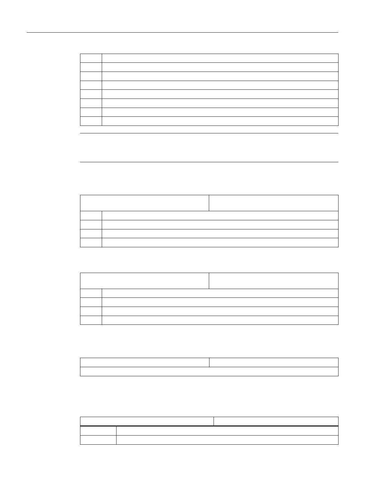
= 2 Auxiliary spindle (driven tool)
= 3 Main spindle (turning)
= 4 C axis of the main spindle (turning)
= 5 Counterspindle (turning)
= 6 C axis of the counterspindle (turning)
= 7 Linear axis of the counterspindle (turning)
= 8 Tailstock (turning)
= 9 Back rest (turning)
Note
To prevent errors occurring, the same axis must be defined as main or counterspindle for all
channels.
Enter the direction of rotation for the rotary axes that are not configured in a tool holder or a 5-
axis transformation via the following channel-specific machine data.
MD52207 $MCS_AXIS_USAGE_ATTRIB[n] Attributes of the axes
[n] channel axis number
Bit 0 Rotates around 1st Geometry axis (for rotation axes)
Bit 1 Rotates around 2nd Geometry axis (for rotation axes)
Bit 2 Rotates around 3rd Geometry axis (for rotation axes)
Bit 3 Reversal of direction of rotation (for rotary axes)
The MD52290 $MCS_SIM_DISPLAY_CONFIG machine data acts only on the OP019. It has
no significance for SINUMERIK 828D.
MD52290 $MCS_SIM_DISPLAY_CONFIG Position of the status display of the channel in the
simulation.
Bit 0 Upper left-hand corner
Bit 1 Upper right-hand corner
Bit 2 Lower left-hand corner
Bit 3 Lower right-hand corner
In the channel-specific machine data, for at least one geometry axis per channel, enter a value
other than 0.0, e.g. 0.001. If the value is 0.0, the system assumes that this parameter has still
not been set.
MD53230 $MCS_SIM_START_POSITION Axis position when starting the simulation
Simulation is only possible if a value not equal to 0 has been set for at least one geometry axis.
Deactivating simulation
The following machine data must be set to deactivate the simulation:
MD51226 $MNS_FUNCTION_MASK_SIM Simulation function screen
Bit 1 = 1 Deactivate simulation
Bit 10 = 1 Hide zero point symbol
Simulation and simultaneous recording
9.2 Setting the technology for simulation
SINUMERIK Operate (IM9)
140 Commissioning Manual, 12/2017, 6FC5397-1DP40-6BA1
 Loading...


