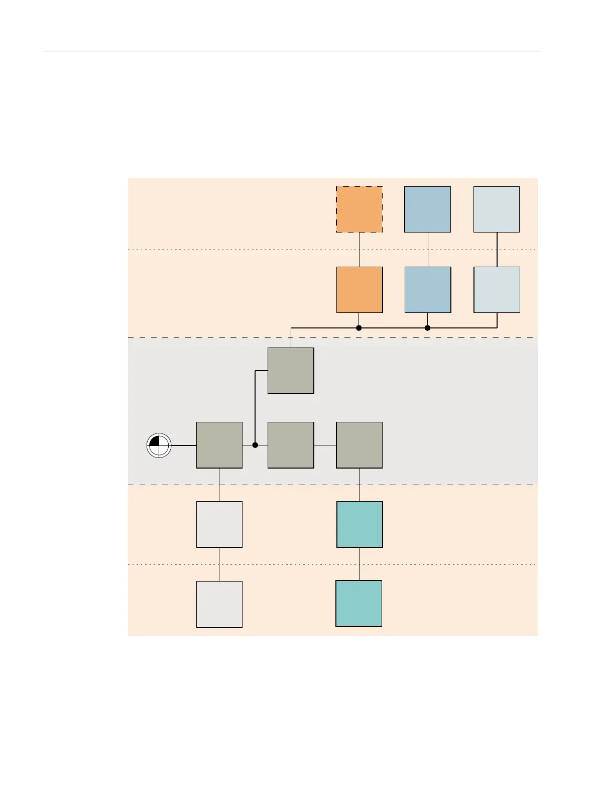
Structure of the geometric machine modeling
The kinematic chain begins with the first offset kinematic element that represents the machine
zero. The other kinematic elements form the linear axes X, Y and parallel Z. The protection
area is used to define the basic bodies of the machine and tools. The movable protection areas
are linked with the associated linear axis; the unmovable protection area is linked with the
offset.
%2;
7DEOH
0$&+,1(
%2;
6WDQG
0$&+,1(
2))6(7
<D[LV
$;,6B/,1
;D[LV
$;,6B/,1
%2;
&</,1'(5
),/(
=D[LV
0$&+,1(
7RROKROGHU
0$&+,1(
7
722/
=D[LV
$;,6B/,1
3URWHFWLRQDUHDHOHPHQWV
3URWHFWLRQDUHDV
*HRPHWULFPDFKLQHPRGHOLQJ
.LQHPDWLFFKDLQ
3URWHFWLRQDUHDV
3URWHFWLRQDUHDHOHPHQWV
Collision avoidance
14.8 Collision avoidance example
SINUMERIK Operate (IM9)
322 Commissioning Manual, 12/2017, 6FC5397-1DP40-6BA1
 Loading...


