Kinematics Swivel head HEAD_2
Rotary axis vector V1 0.000 1.000 0.000
Offset vector I2 0.000 172.000 172.000
Rotary axis vector V2 0.000 1.000
1)
1.000
1)
Offset vector I3 0.000 0.000 93.800
Display version
Swivel mode Axis-by-axis
Direction reference Rotary axis 2
Rotary axes
Rotary axis 1 B Mode Manual
Angular range 0.000 360.000
Kinematics offset 0.000
Hirth joint Yes Angular grid 1.000
Rotary axis 2 C Mode Manual
Angular range 0.000 180.000
Kinematics offset 0.000
1) Calculation of rotary axis vector:
V2: 45 degree angle
V2Y = sin(-45) = -0.7071
V2Z = cos(-45) = 0.7071
V2Y and V1Z can be normalized to 1.
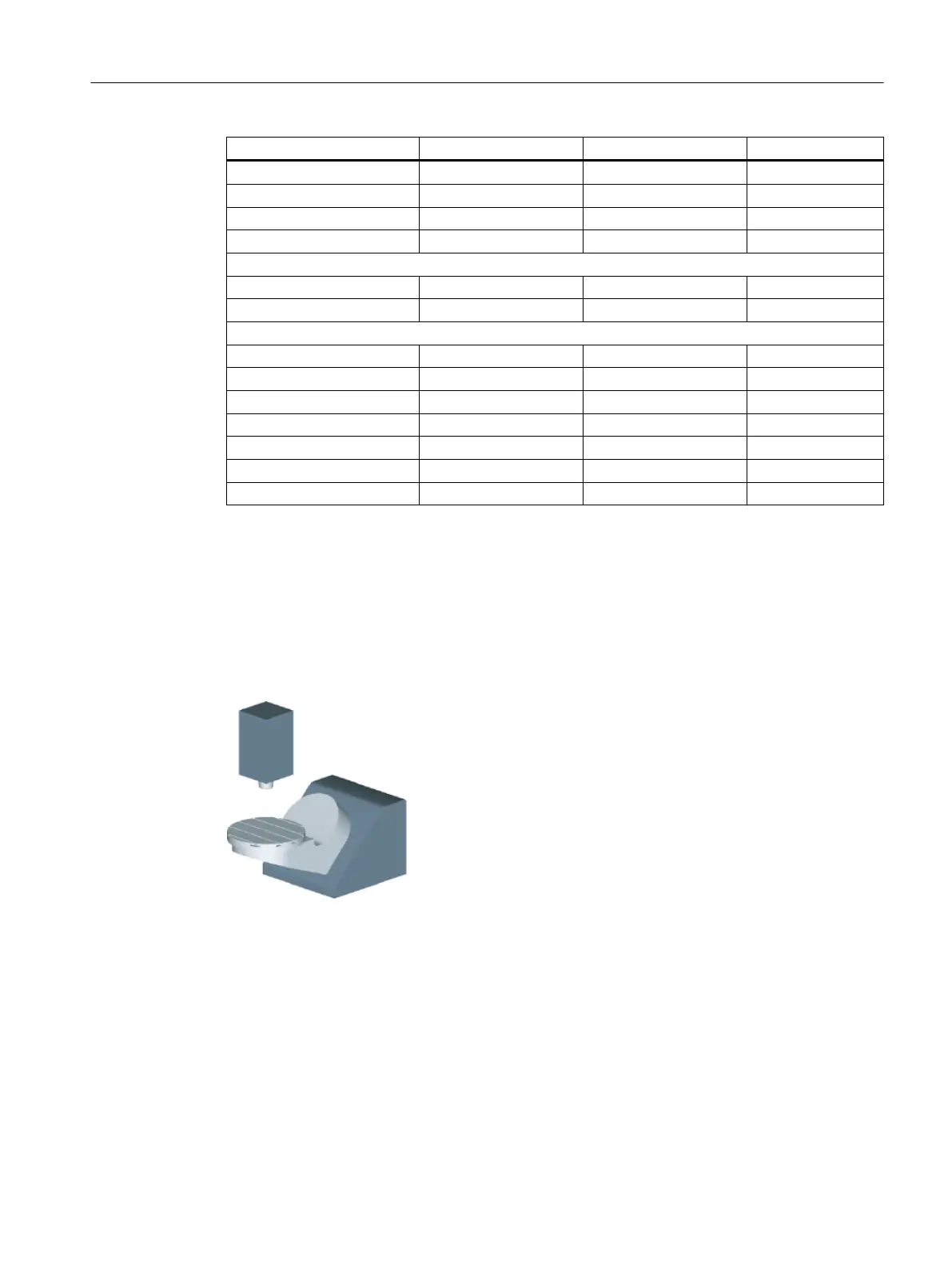
Example 3: Cardanic table "TABLE_45"
The vectors in the drawing refer to the initial setting of the kinematics. The spindle (tool adapter)
is positioned on a gage block above the top edge of the table/center of the table (rotary axis
C). A test mandrel in the spindle is used to determine the center of rotation of rotary axis C.
Technologies and cycles
21.7 Swiveling
SINUMERIK Operate (IM9)
Commissioning Manual, 12/2017, 6FC5397-1DP40-6BA1 581
 Loading...


