References
NCU Manual: Digital inputs / outputs
Setting the switching behavior
You set the electrical polarity of the connected probe using the following general machine data:
MD13200 $MN_MEAS_PROBE_LOW_ACTIVE Polarity change of the probe
= 0 Probe in the non-deflected state, 0 V default value
Probe in the deflected state, 24 V
= 1 Probe in the non-deflected state, 24 V
Probe in the deflected state, 0 V
MD13210 $MN_MEAS_TYPE Measuring type for distributed drives
= 0 Default value
Testing the probe function
You can test the switching function of the probe by manually deflecting it and checking the
following PLC interface signals:
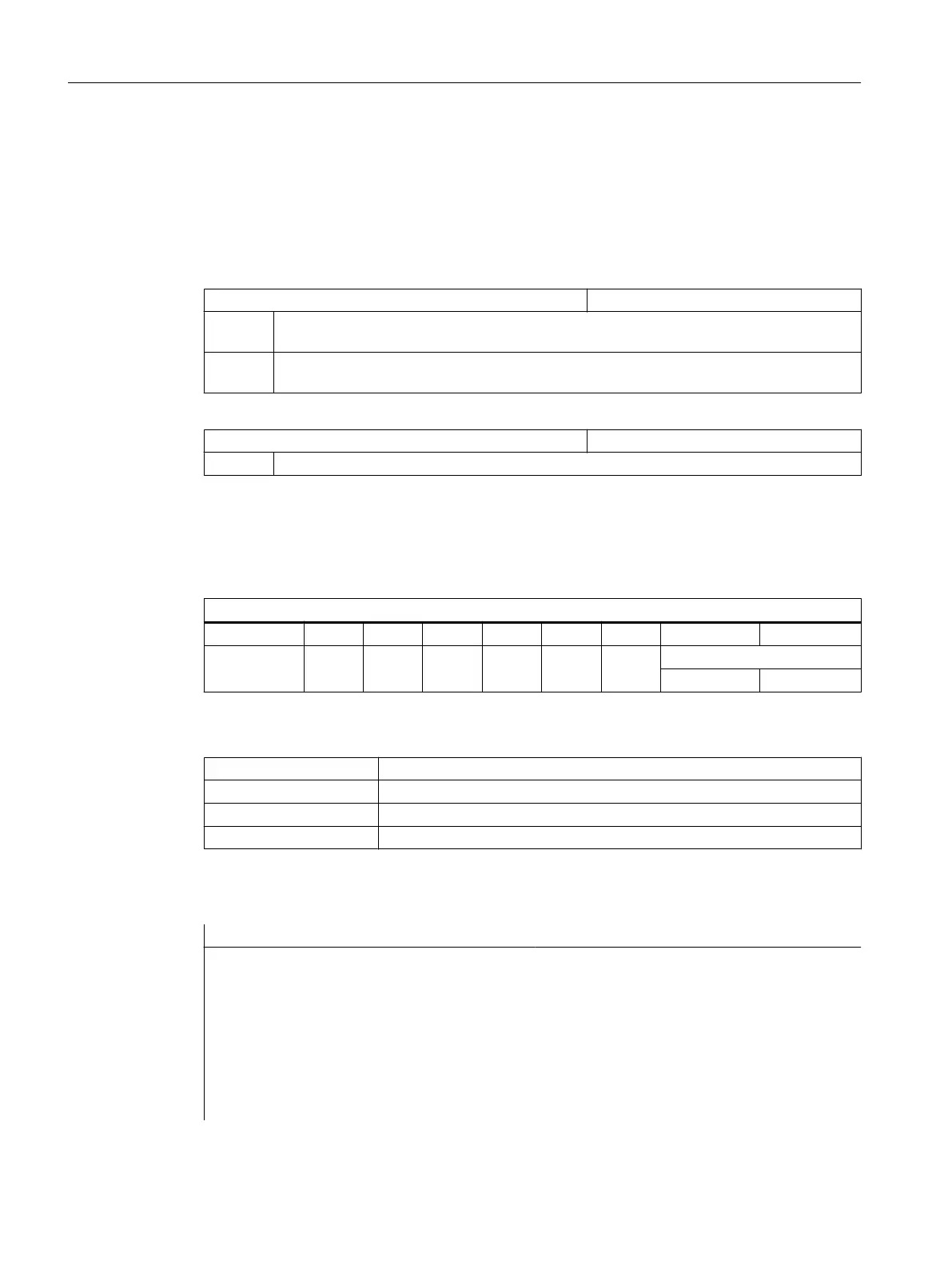
DB 10
Bit 7 Bit 6 Bit 5 Bit 4 Bit 3 Bit 2 Bit 1 Bit 0
DBB107
Probe actuated
Probe 2 Probe 1
To test the switching behavior and the measured value transfer, use an NC test program with,
for example, the following NC commands:
MEAS Measurement with deletion of distance-to-go
$AC_MEA[n] Check the switching operation, n = measurement input number
$AA_MW[axis name] Measured value of the axes in workpiece coordinates
$AA_MM[axis name] Measured value of the axes in machine coordinates
Example of a test program
Program code Comment
%_N_PRUEF_MESSTASTER_MPF
$PATH=/_N_MPF_DIR ;Testing program probe connection
N00 DEF INT MTSIGNAL ;Bit memory to check the switching state
N05 G17 G54 T="3D_Taster" D1 ;Select tool geometry for probe
N10 M06 ;Activate tool
N15 G0 G90 X0 F150 ;Starting position and meas. velocity
N20 MEAS=1 G1 X100 ;Measurement at measuring input 1 in the
X axis
Technologies and cycles
21.10 Measuring cycles and measurement functions
SINUMERIK Operate (IM9)
618 Commissioning Manual, 12/2017, 6FC5397-1DP40-6BA1
 Loading...


