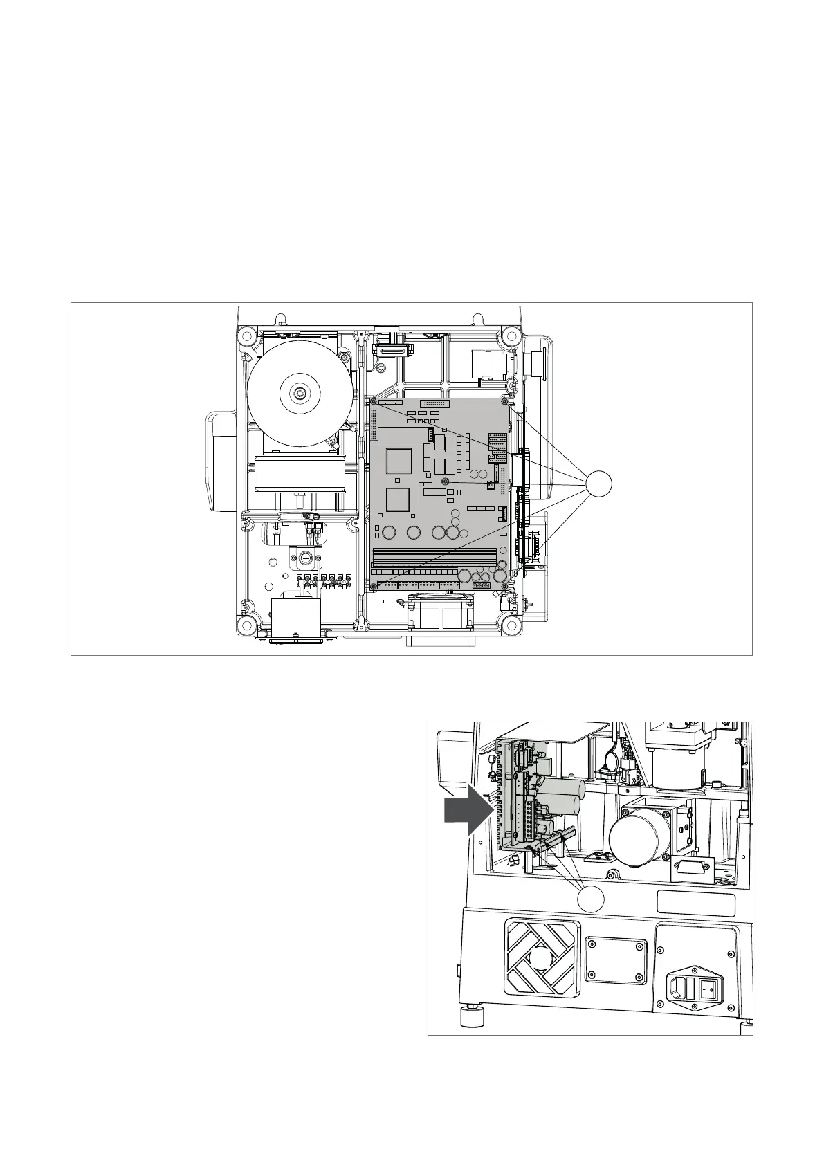
8.12 ELECTRONIC CIRCUIT BOARD REPLACEMENT
1 ) Switch off the machine and disconnect the power lead.
2) Gain access to the bottom compartment (Ch.8.6).
3) Disconnect all the wires from the circuit board.
4) Loosen the nuts (N1) and remove the circuit board.
5) Fit the new board onto the threaded pins and tighten the nuts (N1).
6) Connect all the wires (each connector is polarized and its position cannot be changed).
7) Close the bottom compartment.
8) Carry out the calibration operations (see MACHINE ZEROS; CLAMP; AUTOMATIC CALIBRATION OF TRACER
TOWER DEVICE).
N1
Fig. 60
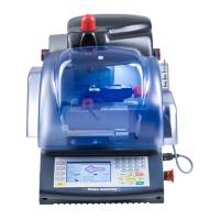
8.13 MOTOR CIRCUIT BOARD REPLACEMENT
1 ) Switch off the machine and disconnect the power
lead.
2) Gain access to the rear compartment (Ch.8.5).
3) Disconnect all the wires from the circuit board connectors.
4) Loosen the 3 xing screws (M4).
5) Remove the circuit board and replace with a new one.
6) Tighten the three xing screws (M4).
7) Connect all the wires to the circuit board connectors
(each connector is polarized and its position cannot be
changed).
8) Close the rear compartment.
Fig. 61
M4
Operating manual TRIAX PRO
Copyright Silca 2016
94