8.10 SENSOR REPLACEMENT
8.10.1 REPLACING SENSOR FOR LOWER AXIS (Y)
1 ) Switch off the machine and disconnect the power lead.
2) Loosen the 2 xing screws (F1) and remove the display stand (Fig. 44).
3) Detach the keypad cable and earth wire as shown in Fig. 46.
4) Gain access to the bottom compartment (Ch.8.6).
5) Loosen the two xing screws and remove the transformer plate.
6) Disconnect the lower Y axis sensor connector from the circuit board.
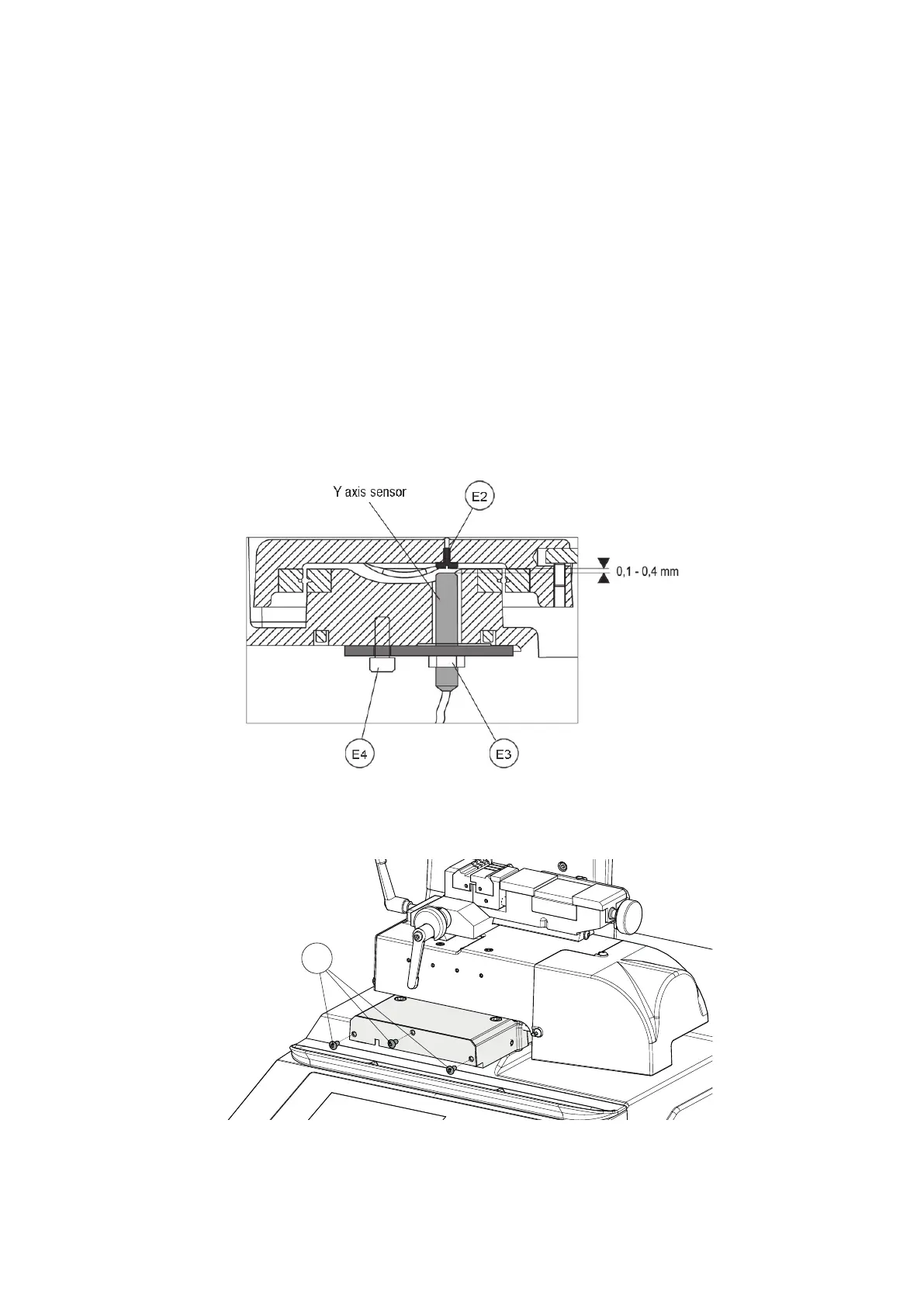
ATTENTION: DO NOT LOOSEN SCREW (E4) !!!
7) Loosen the nut (E3), unscrew the sensor from the plate and remove (Fig. 47).
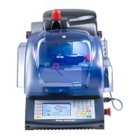
8) Loosen the 3 screws (E1) and remove the lower carriage front cover (Fig. 48).
9) Place the new sensor in position and screw down until it almost touches the screw (E2), then lock the nut (E3).
10) Connect the sensor connector to the circuit board.
11) Replace the transformer plate, lower metal plate and display stand by performing the same operations in reverse
order.
Fig. 47
Drawing references for SENSOR REPLACEMENT AND REGULATION (see MACHINE ZEROS).
Fig. 48
Operating manual TRIAX PRO
Copyright Silca 2016
88