8.15 SAFETY MICROSWITCH REPLACEMENT
1 ) Switch off the machine and disconnect the power lead.
2) Gain access to the rear compartment (Ch.8.5).
3) Loosen the two screws (J1) and remove the microswitch support plate (Fig. 62).
4) Disconnect the wires connecting the two microswitches (J4).
5) Loosen the two nuts (J7) and replace the faulty part.
6) Secure the microswitches with the two nuts and connect the two wires (the wire marked SX on the left and the
wire marked DX on the right).
7) Replace the microswitch support plate with the screws (J1) without tightening them.
8) Adjust the position of the plate so that when the safety shield (V) is moved the microswitches click.
9) Secure the microswitch plate by tightening the screws (J1).
Fig. 64
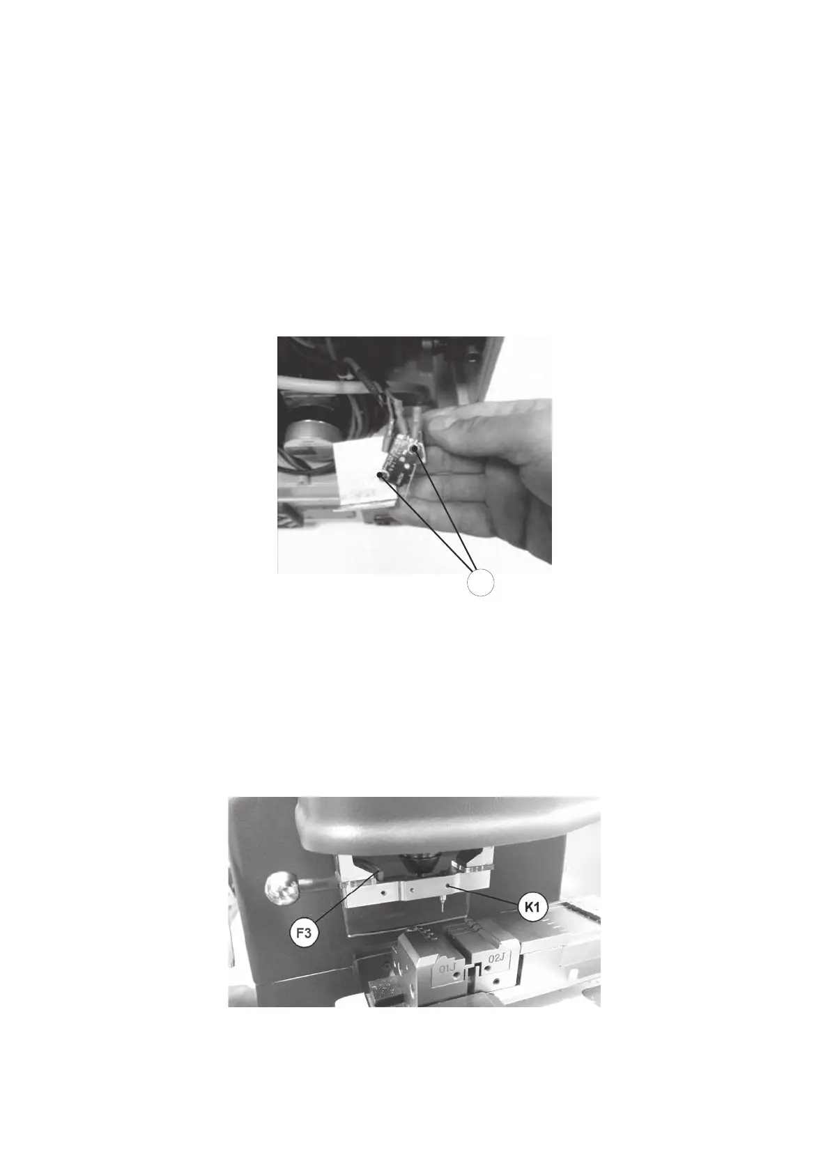
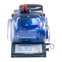
8.16 REPLACING DECODER 04TT (TRACER TOWER)
1) Loosen the screw (K1).
2) Remove the broken decoder from its seat.
3) Place the new decoder in the seat and align with the top part of the TRACER TOWER .
4) Tighten the screw (K1).
5) Calibrate the Tracer Tower.
Fig. 65
Operating manual TRIAX PRO
Copyright Silca 2016
96