C4 User Manual
Page 206 ©2021 Smartrise Engineering, Inc. All Rights Reserved October 25, 2021
NOTE: For most C4 PCB boards, a jumper is used to terminate the CAN bus. For Hall
boards, the termination is set by switching DIP 10 or DIP 12 to ON depending on the
type of Hall board. See Table 10 and Table 11 for switch settings.
Stub Length – A CAN bus resembles a long branch with only short ‘stubs’ coming out of it.
These stubs are kept shorter than 1 ft in length. See Figure 368.
Connections – A twisted pair is used over CAT5 splitters whenever possible. For networks with
over 20 Hall boards, additional power and REF connections will be needed to mitigate voltage
drops.
18.2 Hall Board Status
If problems occur due to hall calls, start by checking the Hall board Status UI menu.
The Hall board status display gives information on each board’s communication status, error
state, connected Riser board, I/O and DIP addressing.
The following procedure describes how to verify Hall board status.
1. Navigate to MAIN MENU | STATUS | HALL BOARD STATUS. See Figure 47.
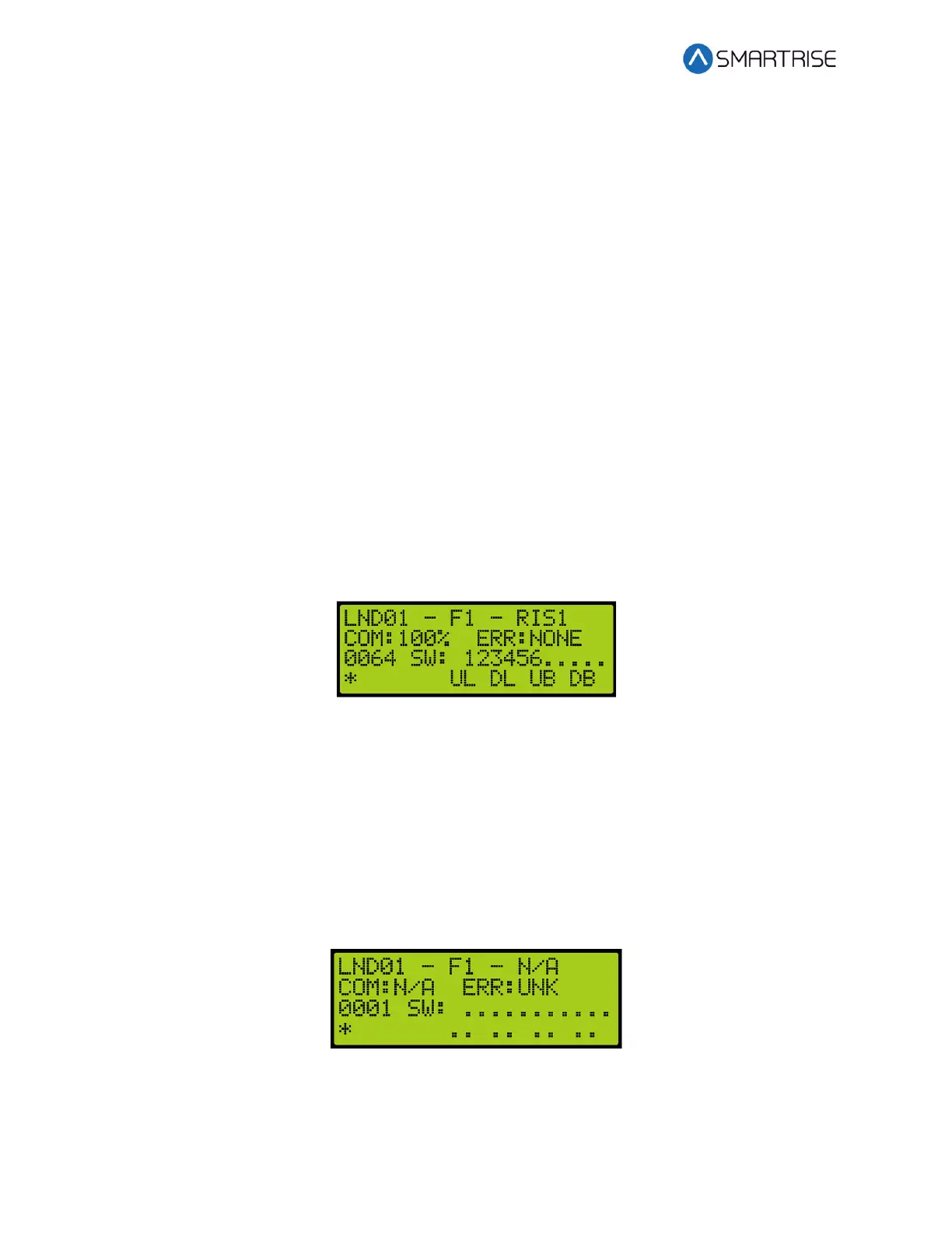
2. The example below shows the Status of the Hall board configured for the 64
th
landing.
Figure 369: Hall Board Status for the 64
th
Landing
The 64
th
Landing example shows the following:
• Belongs to the first function range of Hall boards
• Connected to Riser board 1 in the machine room
• There are no errors
• Both up and down button are currently being pressed
• Both up and down lamps are currently lit
3. The figure below shows an example of the status of an uninitialized Hall board.
Figure 370: Uninitialized Hall Board Status
NOTE: Once communication has been established with a Hall board and the communication is
lost, the com status is 0% instead of N/A.