C4 User Manual
October 25, 2021 ©2021 Smartrise Engineering, Inc. All Rights Reserved Page 25
If there are no Riser boards connected prior to power up, Group Redundancy will not monitor
any Riser boards.
The system has to have additional wiring for the Group Redundancy feature to operate.
• All I/Os between the primary and redundant Riser 1 boards needs to be wired in
parallel.
• All Hall board communication between the primary and redundant Riser 1 boards needs
to be wired in parallel.
• Additional wiring for the relays to control power to the primary and redundant Riser 1
boards.
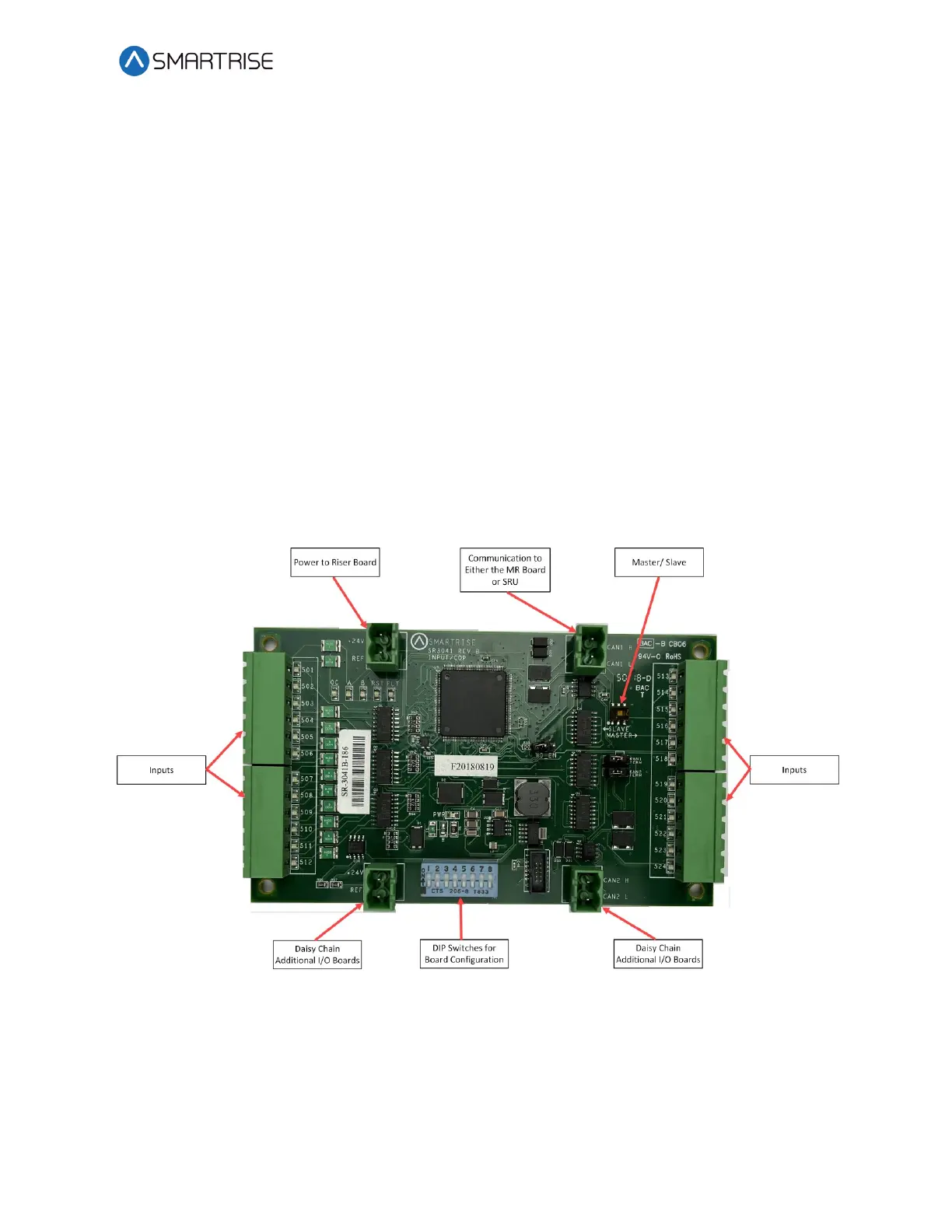
2.4 24 Input Board SR3041
The 24 Input board serves the same purpose as the SR3031 I/O Expansion board with the
exception that there are NO outputs. The 24 Input board has three sets of 8 assigned inputs
which allows for the ability for this board to replace three SR3031 I/O boards. Just like the
SR3031 Expansion board, the 24 Input board can be daisy chained to either the SR3041 or
SR3031 board.
Figure 26: 24 Input Board SR3041
The serial communication is as follows:
• CAN1 – The Master board connects to the COP board’s AUX net.
• CAN2 – The Master board connects to CAN1 of the slave board.
NOTE: CAN2 of each slave board will be connected to CAN1 to the following slave board.