C4 User Manual
October 25, 2021 ©2021 Smartrise Engineering, Inc. All Rights Reserved Page 205
18 Hall Network
The hall network is a group of Hall boards connected by a CAN bus.
18.1 CAN Bus
Each Hall board communicates over a CAN bus to a Riser board located in the machine room.
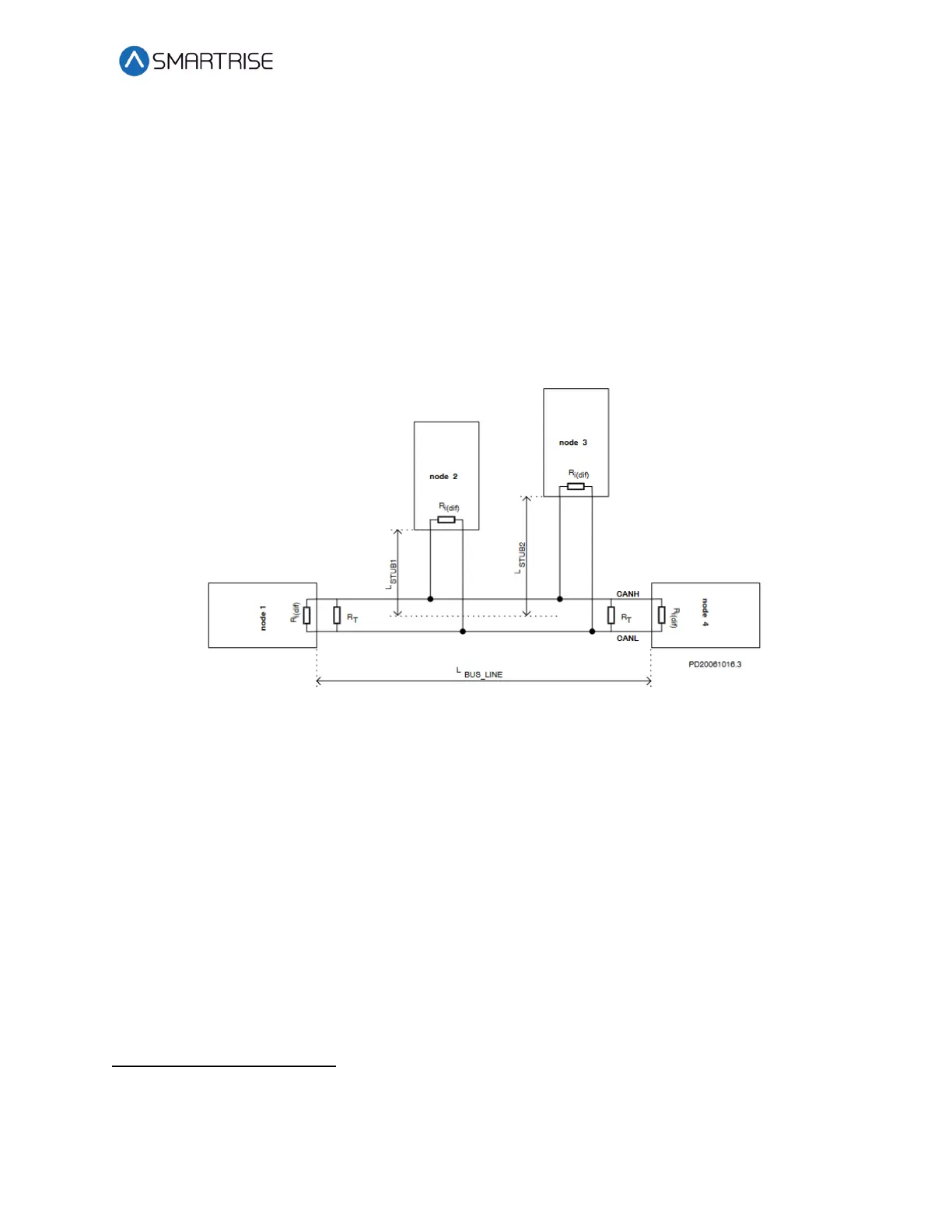
The figure below shows a standard CAN network. For optimal performance, the cable stub
lengths should be kept short and only node 1 and node 4 on the CAN bus line should be
terminated.
Figure 368: Standard CAN Bus
Termination – The first and last boards within each CAN network are terminated. See section
2.3 I/O Board/Riser Board SR3031 for more information.
• Example 1 – A single set of hall buttons are wired to Riser board 1.
• The Riser board’s CAN2 termination and the bottom landing Hall board’s
termination is set.
• Example 2 – Two sets of Hall buttons are both wired to Riser board 1.
• The bottom landing Hall board for each Hall board set is terminated. The
Riser board’s CAN2 is NOT terminated. For tall buildings, the second set of
Hall boards may need to be split off and connected to a second Riser board.
Both networks are terminated as described in example 1.