10 4D Imaging
108 Basic User Manual
6. Adjust the ROI and sample line.
You can press the conrm key to select the desired status icon.
−
If is highlighted, use the trackball to position the ROI.
−
If is highlighted, use the trackball to resize the ROI.
−
If is highlighted, adjust the sample line by positioning the anchor with the trackball.
7. Set the stability, user mode, focus position, image quality and sweep angle.
−
Tap an item under
User Mode
to select a user mode.
−
Tap the Left/Right part of
Sweep Angle
to adjust the sweep angle of probe.
−
Tap the left or right part of
Focus
to decrease or increase the depth of focal zone.
−
Tap the left or right part of
Image Quality
to adjust quality of images.
−
Select the left or right part of Stability to enable or disable the image quality feature.
For other parameters, refer to Section 9.2 Working with 3D Images.
8. Display the 3D imaging in the following instructions.
−
Tap , or , tap
Start
or press the
Freeze
key to display the 4D imaging in a full, dual or quad
display. The system automatically enters the 4D imaging in a quad display by default.
−
Tap
1
,
2
or
4
on the key panel of the touch screen to display the 4D imaging in a full, dual or quad display.
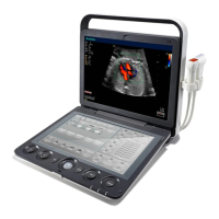
The imaging area of the screen is divided into 3 reference images and a dynamic 3D image by default.
FPS 47
D/G 3/1
GN 255
I/P 3/30
PWR 70
FRQ 3-4.8
D 16.5cm
Angle 55
Map 4
Quality H
Surface
View A
A
B
C
3D
View B
View C
3D Image
Figure 10-2 4D Imaging Screen
As the above gure shows,
●
View A on the top left shows the image on the X-axis.
●
View B on the top right shows the image on the Y-axis.
●
View C on the bottom left shows the image on the Z-axis.
●
The image on the bottom right shows the dynamic 3D image.
As Figure 10-3 shows, the touch screen displays all controls related to the 3D imaging.