6 Acquiring Images
80 Basic User Manual
6. Optimize the PW-mode image. For details, refer to Section 6.5.3 Optimizing Spectral Doppler Images.
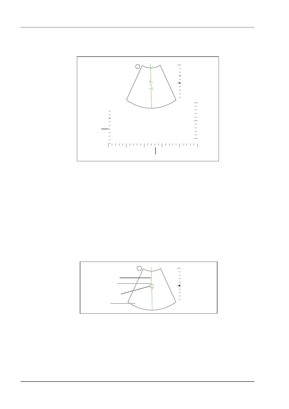
If needed, press the Update key on the control panel to enter the inactivated B+PW mode 2, the following
screen appears.
0
5
50
-50
cm/s
X-axis: Time
Y-axis:
Frequency
S
Figure 6-16 Inactivated B+PW Mode 2 Imaging Screen
You can also adjust the position and angle of spectral Doppler line, the size of sample volume gate, and the
direction of the ow cursor.
7. Press the
PW
key again to exit the screen.
6.5.2 CW Mode
Continuous Wave Doppler (CW) uses continuously transmitted and received ultrasound energy to generate a
spectral display. CW Doppler is used to measure a high velocity, the highest velocity at a specific site, but no
aliasing is created.
Perform the following steps to acquire CW-mode images.
1. Optimize a B-mode image.
2. Press the
CW
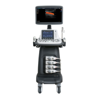
key on the control panel to enter the inactivated B+CW mode 1.
0
5
Spectral Doppler Line
Sample Volume Gate
Flow Cursor
2D Imaging
S
Figure 6-17 Inactivated B+CW-Mode 1 Imaging Screen
−
The spectral Doppler line and the sample volume gate are used to locate the qualitative analysis on the
image.
−
The ow cursor needs to be adjusted parallel to the ow when measuring the velocity.
3. Adjust the position and angle of the spectral Doppler line.
−
Position the sample volume gate on the spectral Doppler line by moving the trackball upwards or
downwards.