6 Acquiring Images
86 Basic User Manual
0
5
0
10
10
5
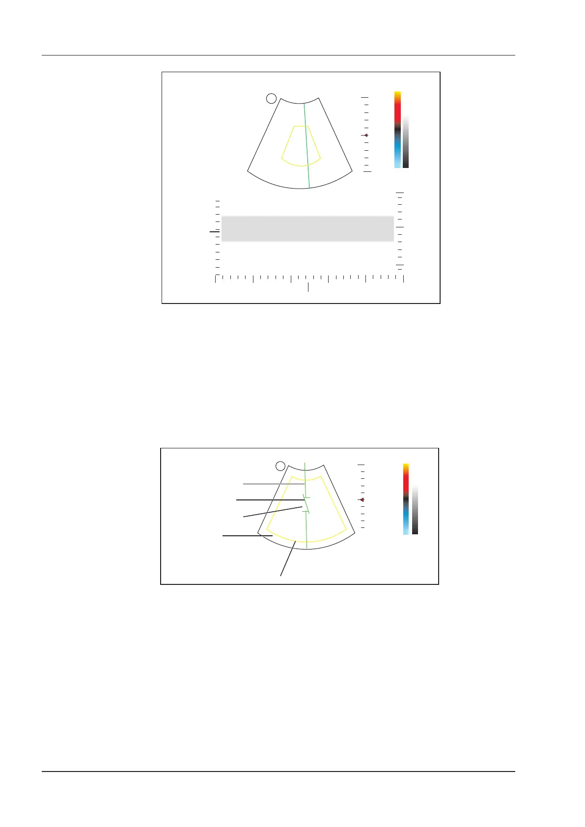
Y-axis: depth
X-axis: time
S
Figure 6-22 B+CFM/TDI +M-Mode Imaging Screen
5. Optimize the M-mode image. For details, refer to Section 6.4.3 Optimizing M-Mode Images.
6. Press the
M
key again to exit the screen.
6.6.2 B+CFM/PDI/TDI +PW
Perform the following steps to acquire the image.
1. Optimize a CFM/PDI/TDI-mode image.
2. Press the
PW
key on the control panel to enter the inactivated B+CFM/PDI/TDI+PW mode 1.
0
5
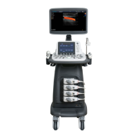
Spectral Doppler Line
Sample Volume Gate
Flow Cursor
2D Imaging
Color ROI
9
-9
cm/s
S
Figure 6-23 Inactivated B+CFM/PDI/TDI+PW-Mode 1 Imaging Screen
3. Adjust the position and angle of the spectral Doppler line.
−
Position the sample volume gate on the spectral Doppler line by moving the trackball upwards or
downwards.
−
Adjust the angle of the spectral Doppler line by moving the trackball to the left or the right.
4. Adjust the sample volume gate.
−
Press the conrm key on the control panel to adjust the size of the sample volume gate.
−
Rotate the
Angle
knob on the control panel to adjust the angle of the ow cursor.
5. Press the
Update
key on the control panel to activate the PW mode.
The PW spectrum is displayed at the lower part of the screen after being activated, as shown Figure 6-24.