2 System Overview
10 Basic User Manual
1 LCD Monitor
2 Touch Screen
3 Coupling Gel Holder
4 Control Panel
5 Front Panel
6 Transducer Cable Hanger
7 Probe Port
8 Power Indicator
9 Charging/Discharging Indicator
10 Battery Capacity Indicator
11 Caster
12 Foot switch Port
13 Pencil Probe Port
14 Probe Holder
15 Engineering USB Port
16 Cable Hanger
17 Speaker
18 Fan
19 Cable Hanger
20 Dust Filter
21 Peripheral Device Panel
22 DVD Drive (optional)
23 USB Port
24 On/Standby Button
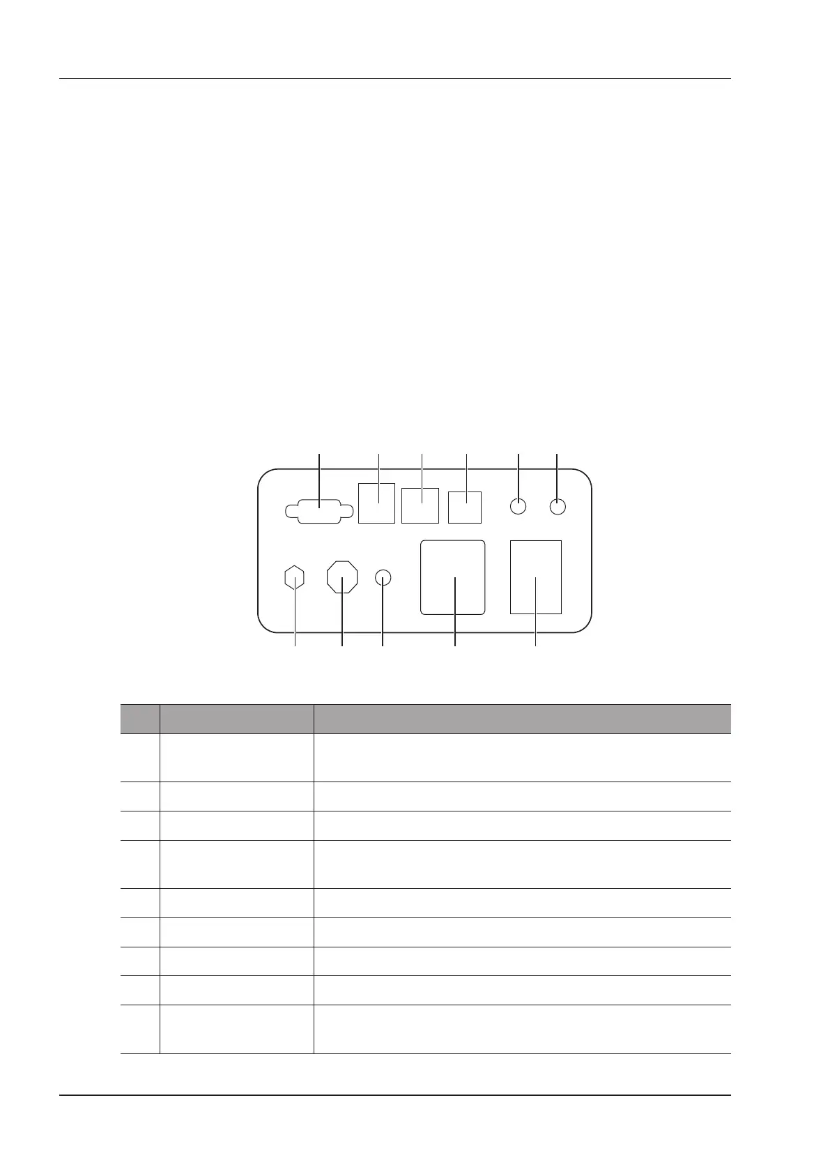
2.2.2 Peripheral Device Panel
1 2 3 4 5 6
7891011
Figure 2-2 Peripheral Device Panel
No. Name Description
1 VGA Video Output Used for connecting a video device to acquire VGA signals, such as
monitor or projector.
2 USB Port Used for connecting the USB devices.
3 Network Port Used for connecting the DICOM server or the network.
4 S-VIDEO Port Used for connecting a video device to acquire S-VIDEO signals, such as
monitor or projector.
5 Audio Signal Output Used for connecting an audio device.
6 Video Printer Port Used for connecting the video printer.
7 Mains Supply Switch Used for powering on or off the system.
8 Power Input Used for connecting the power cable.
9 Equipotential Terminal Used for equipotential connection, balancing the protective earth potentials
between the system and other electrical equipment.