4-11
Processing Instructions Operator Manual 920011-649
f. While control handle is resting on control handle boot frame,
secure split insertion tube sleeve into control handle boot
opening (see Figure 4-6).
Verify split insertion tube sleeve handle is pushed down.
Insertion tube must be inserted over sleeve handle to avoid
possible damage (see Figure 4-10).
g. Once split insertion tube sleeve is correctly positioned and
secured, finish inserting rest of insertion tube in tube slide
(see Fi
gure 4-7).
13. Place endoscope control handle in control handle boot "A". Verify
light guide cable strain relief boot is placed between universal
cord port flaps (see Figure 4-7).
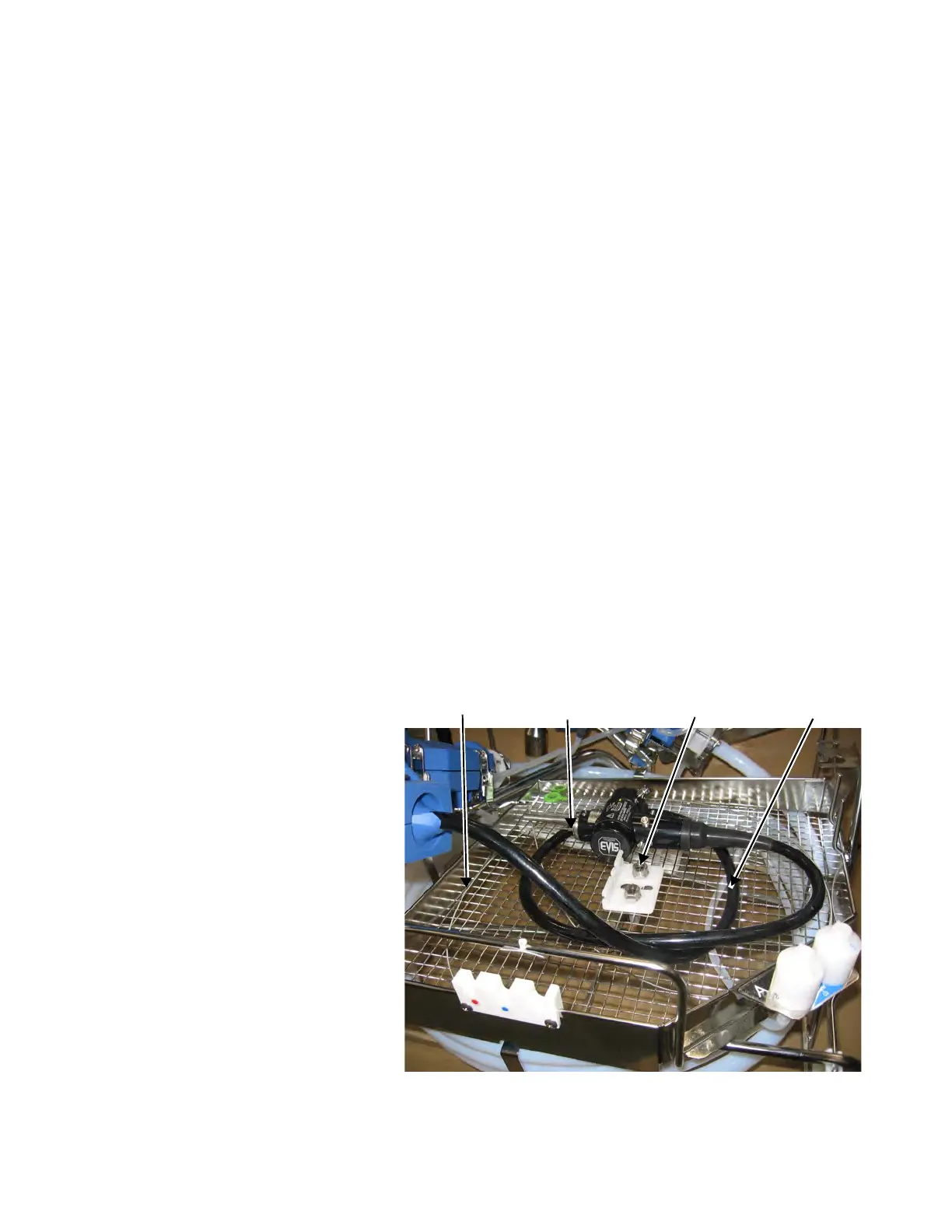
14. Place and coil light guide/ultrasound cables carefully in large
mesh basket (see Figure 4-11). Allow cables to coil naturally. Be
careful not to kink or overbend cable.
15. Rest light guide/ultrasound connectors in large mesh basket. DO
NOT place light guide/ultrasound connectors on top of light
guide/ultrasound cables (see Figure 4-11).
16. If processing a second endoscope, place it in control handle
boot "B", repeating Steps 6 t
o 15.
If only one endoscope is being processed, insert control
handle boot plug into fluid delivery port of control handle boot
"B", as shown in Figure 4-12. Firmly insert control boot plug into
port. Close control handle boot "B".
17. If processing an endoscope identified as requiring use of a Flow
Unit, connect Flow Unit (refer to Endoscope Quick Reference
Guide).
Flow Unit
Connectors
Coil Light Guide
Cable
Channel
Cleaning Brush
Light Guide
Connector
Figure 4-11. Coil Light Guide Cable and Connect
Flow Units