126
S
3. While wrapping bladder around bearing, place
bladder tting into hole where brake line is
protruding.
4. With brake bladder wrapped around bearing,
place half of the raceway back into position with
bladder housed in raceway.
• Using a small at blade screwdriver, slightly
li the rear M6-40 screw so that the raceway
can t back into its specied location
5. Align threaded holes on raceway with holes
from screws.
Note DO NOT remove the screw from its housing, otherwise retrieval of this screw can
become dicult.
6. Tighten M6-40 screws without stripping head
7. Repeat steps outlined above for the other half of the raceway.
8. Replace upper extension arm access hole plugs (if applicable) by inserting into location.
9. Turn supply brake line gas back on pressurizing boom to 75 ± 5 psi and run through functional-
ity of brakes to ensure no audible leaks can be heard.
10. Replace end cap cover by following steps outlined in 1004-400-061
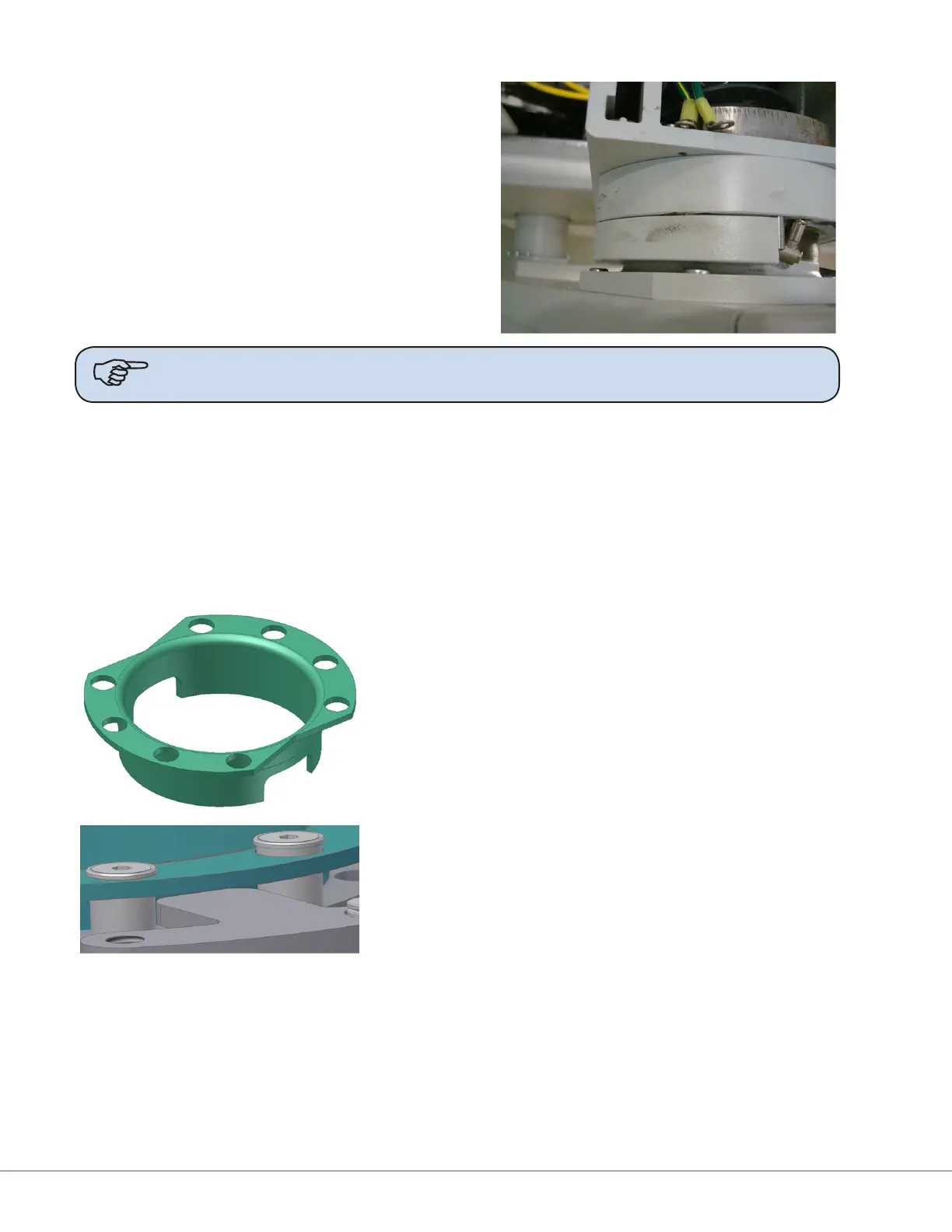
To replace the Protective Collar, do the following:
1. Remove the upper extension arm end cap by following
instructions from 1004-400-061, EDS Installation and
Service Manual.
2. Remove the two M5-25 screws that hold the collar in
place.
3. Back pull cables, conduit, etc. in order to remove the
collar.
4. Install collar into designated location housed within
bearing.
5. Re-install the two M5-25 screws in their designated
location.
6. Pull the cables, conduit, etc. back through the boom.