110
S
16.6 Can Bus Troubleshooting
Caution Follow ESD prevention procedures.
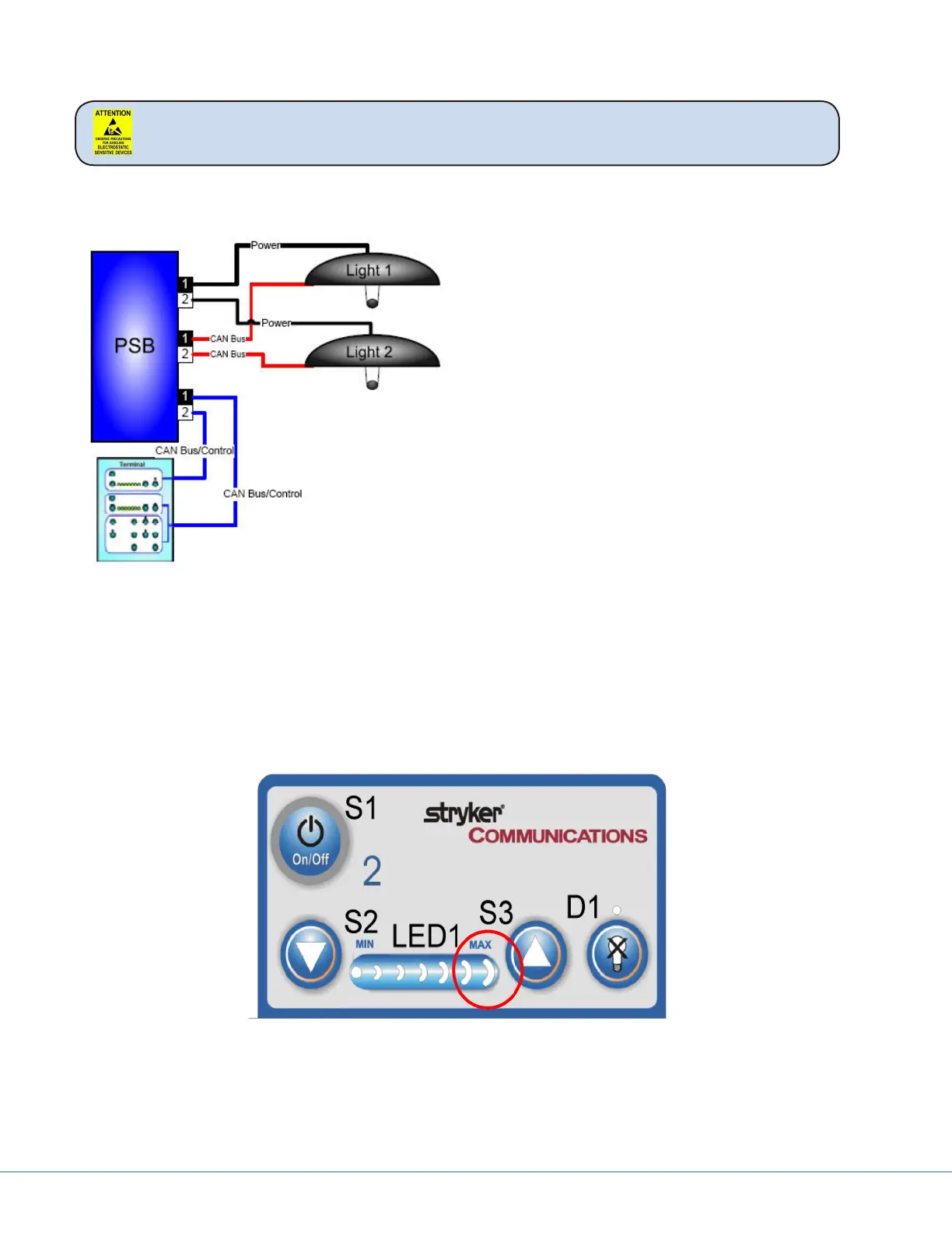
16.6.1 Light Block Diagram
Troubleshooting the light is simplied because
there are two completely independent systems.
e best method for testing is to look at the
symptoms and swap cables to narrow down the
problem. Here are steps to try:
1. Swap Power Cables – check if problem is
in light head or power supply box.
2. Swap CAN Control Cables – check if prob-
lem is in control wiring
3. Swap Touch Panel Cables – check if prob-
lem is in Touch Panel or wiring between
power supply box and Touch Panel
Visum Lighting uses CAN bus technology to control the light and In-Light Camera. CAN bus is a se-
rial digital protocol similar to RS-232. It is carried dierentially over twisted pair wiring. In our appli-
cation it is actually carried over two coaxial cables using the two center conductors.
e shields are used but grounded at dierent points through the signal path and DO NOT make a
continuous electrical path from the power supply box to the Light Control Circuit Board. Most control
problems are due to a broken CAN Bus connection. is will be evident by the last LED on the Light
Control Touch Panel blinking.
To troubleshoot this issue take o the cover of the light head and perform continuity checks from the
light head back to the power supply box.
e CAN+ is on the brown coaxial center conductor and the CAN – is on the clear center conductor.