107
S
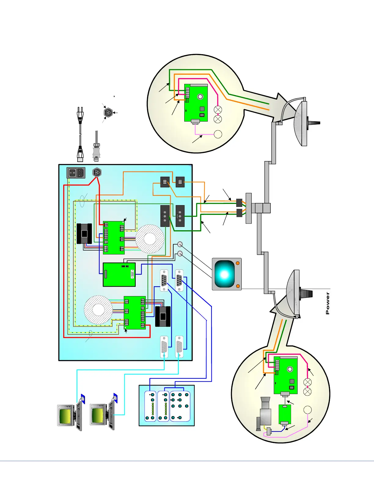
16.5.6 Connection Structure of Systems
e wiring for the whole system is shown below.
Power Supply Box with Safety Power
X4
X2
PE
-Lamp2
-Lamp1
+Lamp
+Vin
-Vin
uC
Heatsink
1
1
X1
ROM
1 2 1 21 2 1 21 2 1 2 1 2
1 2 1 2 1 2 1 2 3 1 2 1 2 1 2 1 2 1 2
1 2 1 2
1 2 1 21 2 1 21 2 1 2 1 2
1 2 1 2 1 2 1 2 3 1 2 1 2 1 2 1 2 1 21 2 1 2
1 1
1
1
Power Supply 2
Power Supply 1
Video
Demodulator
Main Power
Input
1 th Power supply
Main Power
2 th Power supply
Secondary
Primary
Primary
Light Power 1
Light Control 1
Control 1
BNC
S-VIDEO
X4
X2
PE
-Lamp2
-Lamp1
+Lamp
+Vin
-Vin
uC
Heatsink
1
1
X1
ROM
M
M
Control 2
Terminal 1
Terminal 2
Light Power 2
Light Control 2
Transformer
2
Transformer
1
Terminal
Power Box
Monitor
Control 2
Control 1
Light 1
with Camera
Light 2
without Camera
Armsystem
Main Power
Connection
1
Secondary
Heatsink with
Bridge Rectifier
Heatsink with
Bridge Rectifier
Steuer-
elektronik
Steuer-
elektronik
Video
Modulator
Camera
Wall Control Light 1
Wall Control Light 2
Light Control 1 (CAN)
Light Power 1 (24VDC)
Light Power 2 (24VDC)
Light Control 2 (CAN)
Light Power 1 (24VDC)
Light Control 1 (CAN)
Power to halogen bulb
Light Power 2 (24VDC)
Light Control 2 (CAN)
Power to halogen bulb
Control Light 1
Control Light 2
Earth
Screw
Earth
Screw
Combined Camera,
Motor and Power
Changing Motor
Changing Motor
24VDC
Safety Power
-
+
Earth
24VDC / 16A
Safety Power Female Connection
L = +
N = -
= Earth