58
S
Strain Relief Plug
d. Pass the small end of the cable provided
with the handle through the strain relief
and into the FLEXiS System.
e. Connect the cable to the secondary con-
trol cable inside the FLEXiS System.
f. Connect the cable to the D-sub connec-
tor on the bracket.
g. Measure the appropriate amount of
slack and install the strain relief plug
around the cable and into the bottom of
the FLEXiS System.
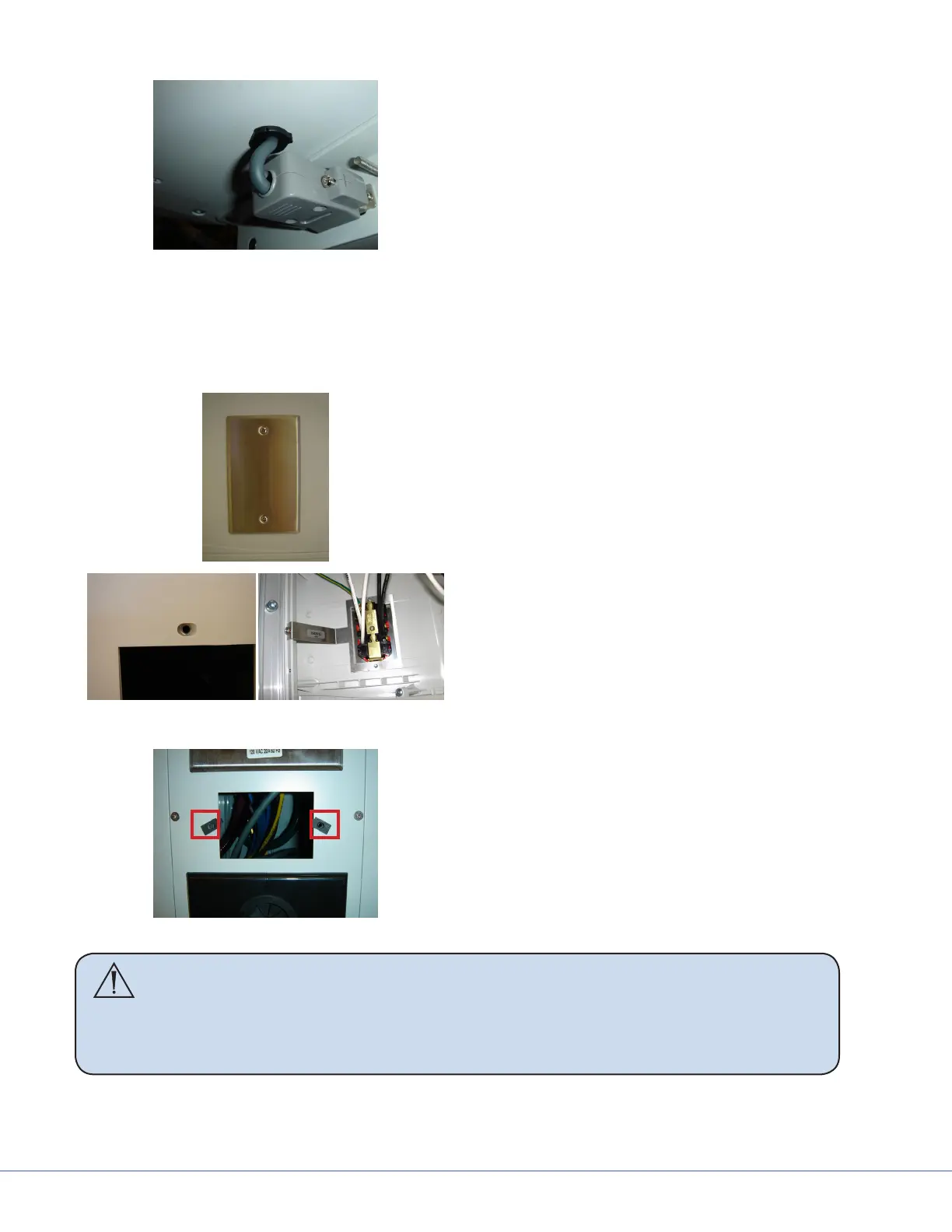
11.1.4 Installing Auxiliary Plates
1. Locate a blank plate location to install the
auxiliary plate.
External View Internal View
2. Remove the two (2) 6-32 screws that hold
the plate attached to the service head.
ese screws are held in place by either
a grounding bracket with pem nut (side
modules) or metal screw clips (front or
back plate), so there are no screw nuts to
account for.
Screw Clips
3. Route the appropriate cables through the
opening and connect to the auxiliary plate.
4. Push any slack from the cable back into
the plate opening and install the auxiliary
plate with the two (2) 6-32 screws that
were removed in Step 2.
WARNING Low voltage plates, medical gas, and video connection plates cannot be
installed in the same side module as electrical outlets. Reference the proj-
ect drawing for specic locations to install data or other low voltage plates.
Contact a Field Engineer for any deviations to the project drawing for ap-
proval