22
S
10. Use a Torpedo Level to verify that the down tube ange is level across three horizontal planes.
11. Connect the ground wire (found on the down tube ange) to the ground lug located in the ceil-
ing.
12. Refer to Section 7 to complete installation.
6.3 Flat Panel
1. Place the suspension onto a heavy machin-
ery li device.
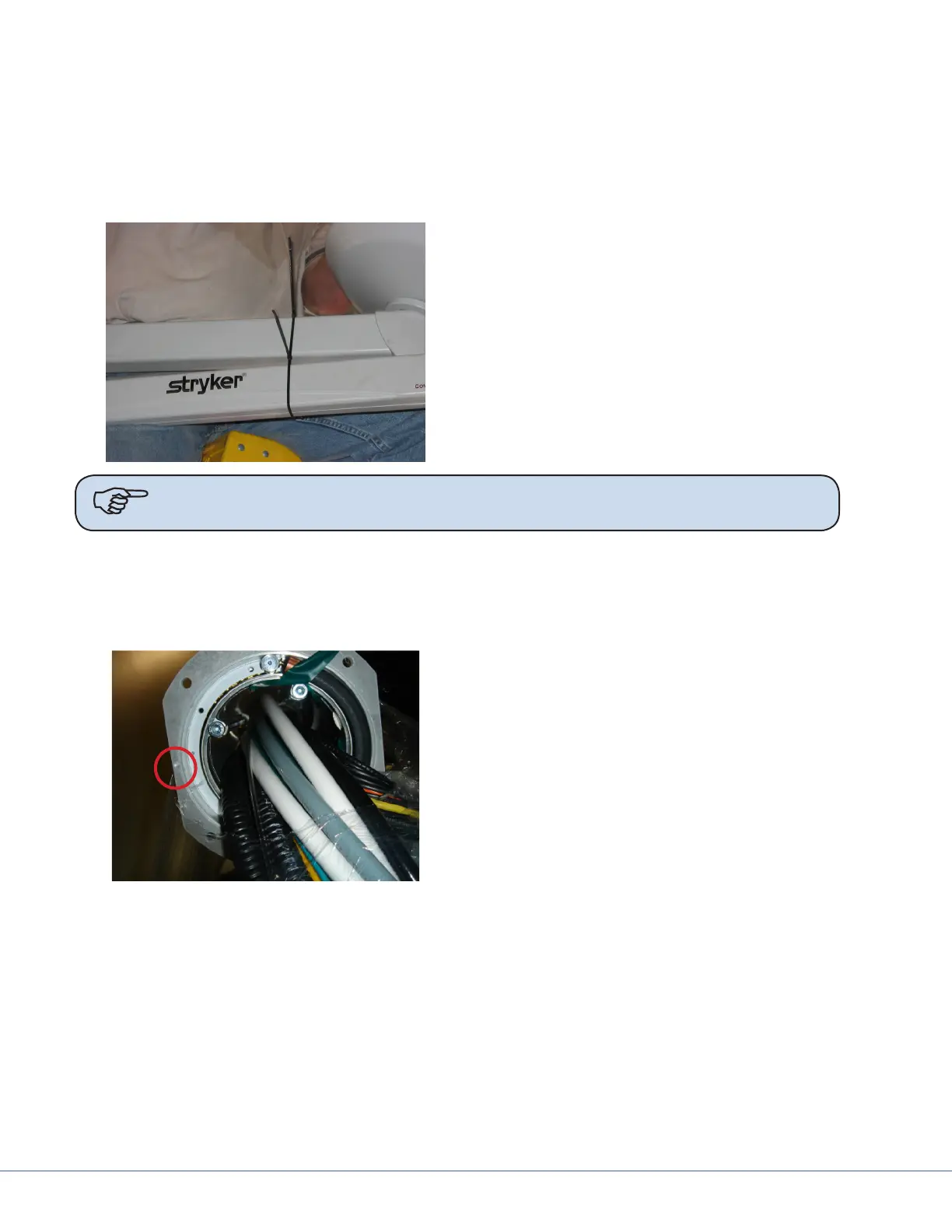
2. Use zip ties to tie the horizontal arm and
Spring Arm together to prevent swinging
during installation.
3. Raise the Flat Panel Arm for installation;
position the arm so the stop is in the speci-
ed location (the Project Manager should
have this information).
Note e normal stop position is above the bed, allowing 330° of rotation of the upper
arm, with the 30° “dead” spot.
6.4 Booms
Due to door entry height, the ange and drop tube may be removed for entry into the room. e
ange and drop tube must be reinstalled before installation of the equipment boom.
If the MMP200/OSC600 Service Head is not as-
sembled:
1. Place pallet securely on material li (e.g.,
Genie Li).
2. Determine the orientation of the ser-
vice head before attaching to the down
tube, feel for the notch. e notch will be
mounted to the front of the service Head.