101
S
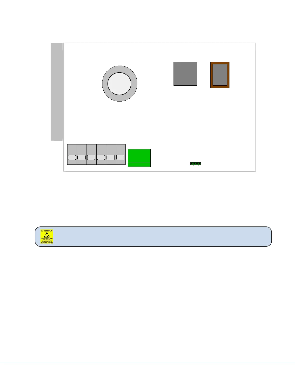
16.4 Plug Layout of the Electronic Control System
e location of the plug-in connections on the electronic control system is shown below.
X4
X2
PE
-Lamp2
-Lamp1
+Lamp
+Vin
-Vin
uC
Kühlbalken
Schutzerde
Minus Versorgung
Plus Versorgung
Gemeinsame Lampenleitung
Gegenpol Lampe1
Gegenpol Lampe2
CAN + Anschluss
optinaler Ein.- Ausgang
1
1
CAN - Anschluss
CAN Schirm
X1
ROM
Heat Sink
Protective Ground
N/A
CAN - Connection
CAN Screen
CAN + Connection
Light Two -
Light One -
Common Lamp Line
+24VDC
Common 24VDC
WARNING Follow ESD procedures to prevent damaging sensitive equipment.
16.5 Plug Allocation
e following section describes the plug-in connections of the electronic control system.
Plug-in connection X3 to the power plug
Pin no.
• PE / protective grounding
• Supply voltage, negative
• Supply voltage, positive
• Joint lamp cable, positive, for lamps 1 + 2
• Negative lamp cable for lamp 1
• Negative lamp cable for lamp 2
Plug-in connection X2 to the CAN plug
Pin no.