24
S
1. Remove the six (6) Allen screws from the
Service Head using a 5mm Allen wrench.
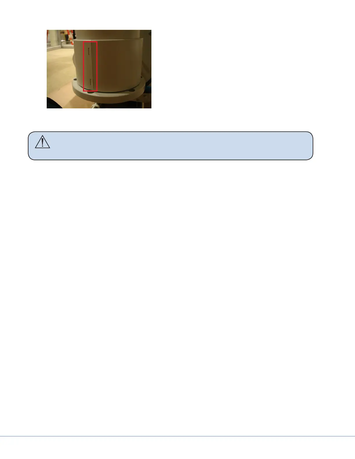
2. Remove the cylinder cover located on the
Down Tube. e two (2) halves can be de-
tached by depressing on the two (2) clips
with a at edge tool.
3. Rotate the Down Tube and determine the
stop location. is point will be installed
to the front of the service head.
4. Locate the cable kit end and pass through the service head opening. In some cases, half of the
pass-thru plate will need to be removed to feed the cable kit completely through.
Caution Be sure to leave enough slack for the EP Module control cable within the
arm set. Failure to do so may result in damage to the cable upon removal
of the EP module.
5. Attach the service head by inserting and tightening the six (6) Allen screws to 7.4 lb- (10 Nm)
using a 5mm Allen wrench.
6.5 Routing Cables
is section is only applicable to suspensions with lengthy cable kits.
1. Uncoil the cable kit.
2. Pull the cables from the suspension through the top of the mounting interface plate.
3. Continue to route the cable through the ceiling conduits. Consult your Project Engineer and/or
room drawings to determine cable routing through the conduits.