19
S
6. Preparing the Suspensions
6.1 Installing the Cable Kit for Lights
1. Route the power and control cables between the power supply box and the suspension structure.
Verify that the light connectors remain near the ceiling plate, as shown in the gure below.
2. (For LED only) Route the S-Video cable through the pre-installed conduit between the super
structure and video output location.
Note Consult your Project Engineer and/or room drawings to determine the video
output location.
3. Pull the cable between the wall control unit and the power supply box.
One end of the wall control unit cable is unterminated.
4. Cut the wall control unit cable to length and terminate it. Connect the wires into the female
connector according to the schematic chart shown below.
Schematic
P1 P2
RED
BLK
WHT
GRN
SHLD
Schematic
P1 P2
SHLD
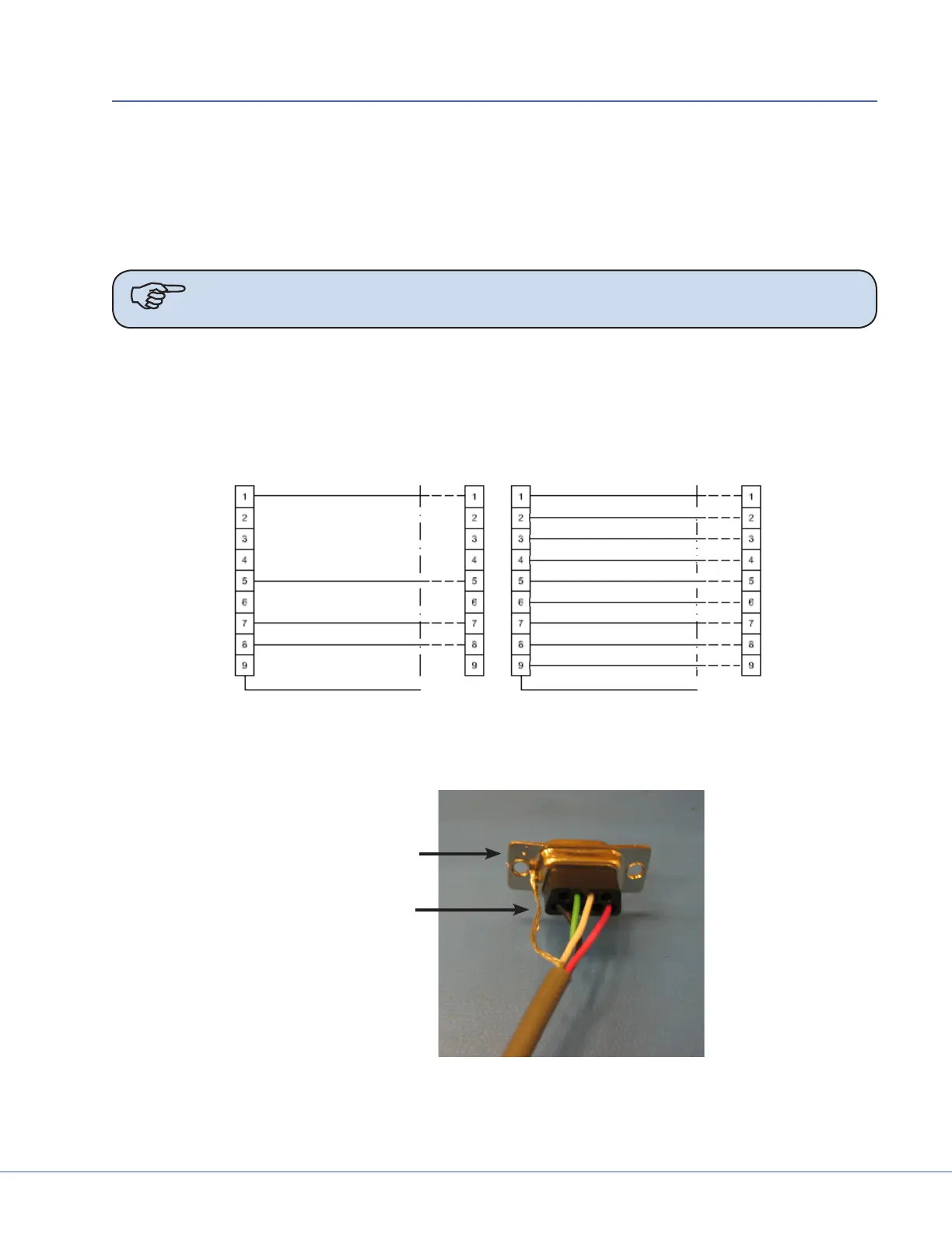
Wall Control Unit Cable Pin Conguration - LED (le) Halogen (right)
5. Solder the Shield Conductor to the DB9 female connector chassis as shown below.
DB9 Female
Connector
Shield Conductor
Soldered Shield Conductor