48
S
15. Attach the shroud to the back of the Adjustable Yoke using the four knob screws.
WARNING Ensure that all screws are present. Missing screws could result in the yoke
falling.
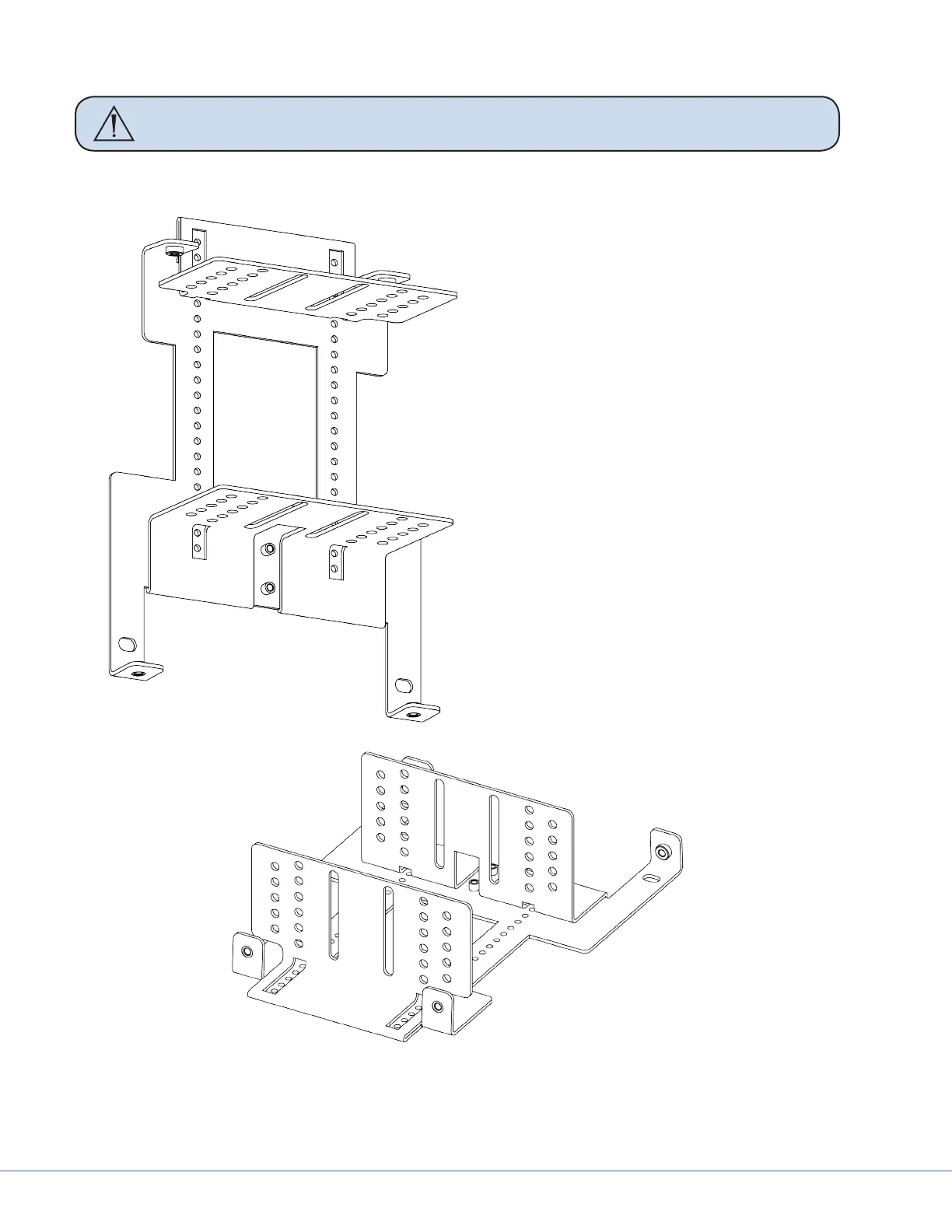
10.4 Balancing the Monitor
1
11
10
9
8
7
6
5
4
3
2
1
10
9
8
7
6
5
4
3
2
When the monitor is balanced correctly
and the brakes are properly adjusted, the
yoke will always hold the position in which
it is placed throughout its range of motion.
Improper balance and brake adjustments
may result in the monitor driing when it is
released. e vertical and horizontal ad-
justments of the yoke center of gravity are
accomplished by changing the position of
the Monitor Vertical Adjust Bracket either
on the back of the monitor, in relation to the
Central Monitor support bracket, or both.
To test balancing and brake adjustment,
move and release the yoke in various posi-
tions throughout it’s range of motion. If the
monitor dris in any position, use Table 10.2
to determine where the center of gravity
is located; use Table 10.1 as an adjustment
guide. Note that the yoke’s center of gravity
may require adjustment in both the vertical
and horizontal directions (for example top-
heavy or bottom-heavy). If the monitor still
continues to dri, tighten the brakes.
10
8
6
4
11
9
7
5
3
2
1
11
9
7
5
3
1
10
8
6
4
2
Monitor Vertical Adjust Bracket (see Table 10.1)